An Introduction To Seals types ,Selection And Applications
Introduction
Seal is a device or substance that is used to join two things together so as to prevent them from coming apart or to prevent anything from passing between them.Seals are an important part of machine design in situations where the following conditions apply:
1. Contaminants must be excluded from critical areas of a machine.
2. Lubricants must be contained within a .space.
3. Pressurized fluids must be contained within a component such as a valve or a hydraulic cylinder.
Excessive leakage in a hydraulic circuit reduces efficiency and results in power loss or creates a housekeeping problem or both.Hydraulic seals prevent leakage by closing off oil passageways; they seal the gaps to prevent fluid loss.
Seals Classification
The purpose of seals is to contain the working fluid within the hydraulic or pneumatic unit and to keep external contamination out. They may be classified as one of the following.
1- Static seals,
2- Dynamic seals
• Sliding seals
• Rotary seals.
1-Static Seals
A static seal is one that is compressed between two rigidly connected parts to seal the fluid passage and has a compression of approximately 25 per cent.
Stationary seals are used between the flanged joints of pipes, on the cylinder heads of engines pumps and compressors, between crank cases and oil sumps and under inspection and access covers.
Sometimes a liquid sealant is used and there are many proprietary brands that are resistant to oil and water. Some of them solidify after assembly whilst others are intended to remain tacky.
Separation of the surfaces for maintenance can sometimes be a problem after which they have to be carefully cleaned before re-assembly.
1-1 GASKETS
Gaskets are cut out of thin sheets of material and placed between mating surfaces which are then squeezed together by screws or bolts. The materials used are paper, copper, brass, rubber and so on. Typical applications are between flanges on pipes and flanges on the fluid port of a pump or motor.
 |
| FIG 1 |
Types of Gaskets
1. Non- Metallic
2. Semi- Metallic
3. Metallic
 |
| FIG 2 |
1-2 RINGS
Rings are placed in grooves between the mating surfaces and stand proud of the groove so that they are squeezed when the surfaces are pulled together. The rings are usually circular in section and are then called O rings but they may have rectangular sections also.
 |
| FIG 3 |
static axial seal
A static axial seal acts similar to a gasket in that it is squeezed on both the top and bottom of the O-ring’s cross section. (figure 4)This type of seal is typically employed in the face (flange) type applications
Static Axial Seal Gland
 |
| FIG 4 |
Static Radial Seals
Static Radial Seals are squeezed between the inner and outer surfaces of the O-ring. They are typically employed in cap and plug type applications,
Static Radial Seal
 |
| FIG 5 |
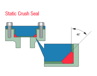
STATIC CRUSH SEALS
In crush seal applications, the O-ring is completely confined and pressure deformed (crushed) within a triangular gland made by machining a 45° angle on the male cover. Squeezed at an angle to the O-ring’s axis, crush seals are used in such simple applications
STATIC CRUSH SEALS
 |
| FIG 6 |
STATIC SEALS WITH DOVETAIL GLANDS
O-rings are sometimes employed in static or slow moving dynamic situations calling for specially machined “dovetail” glands. Because of the angles involved, controlling the tolerances in these glands may be difficult.
The purpose of these glands is to securely hold the O-ring in place during machine operation and/or maintenance disassembly.
A typical valve seat application In this application, O-ring squeeze is primarily axial in direction (valve operation exerts force on top and bottom seal surfaces).
To avoid tearing or nicking, the use of O-ring lubrication is recommended while installing the O-ring into the dovetail gland. Because of the difficulty in creating the groove and tight tolerances required, this type of seal application should only be used when necessary.
STATIC SEALS WITH DOVETAIL GLANDS
 |
| FIG 7 |
Back-up rings
Back-up rings are plastic or rubber rings used to prevent the O-ring from entering the clearance gap. When high pressures are exerted on the O-ring, its soft rubber material can be forced into the clearance gap causing the O-ring to extrude
 |
| FIG 8 |
METAL O RING SEAL
Metal O Rings are a superior sealing method, these seals are created to improve the capability in intense operations. Used in many cases where elastomers don’t provide sufficient reliability for certain applications. They have the capability to withstand wide scope of temperatures, corrosive chemicals, high pressures, and radiation. Metal O Rings are commonly made from tubing. A classic tubing is made out of stainless steel and high-temperature alloys. this divided to :
- metal O ring seal
- metal C ring seal
- metal E ring seal
 |
| FIG 9 |
1-3WASHERS
Sealing washers are placed under the head of screwed fittings with parallel threads to prevent fluid leaking up the thread and escaping under the head. Plastic washers are sufficient for pneumatic applications and copper washers are also often used.
 |
| FIG 10 |
DOWTY (Bonded) WASHERS
These are used for containing high pressure fluids. They are usually aluminium rings with a rubber seal glued to the inner surface. The shape of the seal is such that fluid leaking up the thread presses the rubber firmly against the sealing surfaces.
 |
| FIG 11 |
2- Dynamic seals
A dynamic seal is one that is installed between two parts that move relative to one another, for example on a rotating shaft or a sliding piston. The sealing principle requires the seal to be compressed slightly (approximately 10 per cent) during installation. The seal is allowed to flex in the sealing chamber and a mechanical or fluid pressure forces the seal to distort and block the passageway.
These seals require lubrication during movement or sealing
This classification of seals is used in situations involving reciprocating (sliding), rotating or oscillating motion.
Dynamic seal performance may be substantially affected by a number of operating environmental factors.
2-1 Sliding seals
Sliding seals are mainly used with cylinders to prevent fluid escaping around a piston rod or from passing from one side of a piston to the other. All sliding seals are rings but many different types exist. These may be solid rings such as O rings or rings with rectangular sections. For more demanding applications, more sophisticated designs are used with lips or cups to make the seal fan out and fill the gap between the sliding parts.
Reciprocating seals.
As depicted in figure 12 , are used in situations involving a moving piston and a rod. These seals constitute the predominant dynamic application for O-rings.
For optimum performance of reciprocating seals, careful consideration of the following factors is
required
 |
| FIG 12 |
Common types are U ring, Cup, Flange, Chevron, O ring and T ring
The figure 13 shows a U ring seal on a piston to prevent fluid passing from the top to the bottom of the piston. Two seals placed back to back would be used for a double acting cylinder. U ring seals may be used for piston rods also and there is a large variety of shapes for shapes for different applications.
 |
| FIG 13 |
Cup seal
which is suitable for simple single acting cylinders with low pressure. The fluid pressure forces the cup out against the cylinder walls.
Flange seal
which is used on the piston rod. The flange is tightened down and squeezes the seal into the gap between the rod and the cylinder end.
 |
| FUG 14 |
chevrons Seals
The seal is made up of
chevrons embedded in a softer material. They are forced into the gap by the screwed ring and the chevrons spread out and form a seal.
The wiper ring
The wiper ring
is not strictly a seal. Its purpose is to remove oily dirt from the rod as it is drawn into the cylinder. The action is similar to that of a car wind screen wiper.
 |
| FIG 15 |
Piston ring
Piston rings are metallic piston rings used to seal cylinders. They have a higher working temperature than elastomeric, fabric, or polymer materials. Piston rings are available in a variety of configurations, including compression rings, split rings, and cord rings.
 |
| FIG 16 |
Exclusion seals
Exclusion seals (figure 17) are dynamic seals such as wipers and scrapers that support sliding or reciprocating motion. They clean the surface by scraping abrasive particles such as dirt, mud, and ice. Exclusion seals are very important because they protect the seal and extend its service life. The wipers should be checked frequently to ensure they are in good working condition. Often the wipers fail causing the seal to fail.
 |
| FIG 17 |
Packing's and Braided Rope Seals
Rope packing's used to seal stuffing boxes and valves and prevent excessive leakage can be
traced back to the early days of the Industrial Revolution.
Compression packing seals or gland seals are used to seal a variety of fluids under a range of conditions (figure 18). They are used to help contain water, acids, solvents, gases, oil, and other chemicals that are subjected to various temperatures and pressures.
Compression packing is a common sealing process where a gland along the top ring is tightened, and the packing compressed onto the surface to be sealed.
 |
| FIG 18 |
The packed gland seal for pump applicataions is, due to it's high maintenance requirements, is now rarely fitted to new pumps then mostly in conjunction with long coupled bed plate mounted pumps. Specific operating conditions require distinctly different types packed gland seals.
They require regular checks and maintenance adjustments.. Proper lubrication of the gland packing requires a certain leakage rate.
Special manufacturers recommendation's are to be observed individually. Service life expectancy is between 1 and 2 years, this can sometimes extend to several years on favourable conditions. Extremely bad fluid conditions (sediments, additives, overheating) can however drastically cut short their service life.
Packed glands should preferably be used in conjunction with shaft sleeves in order to avoid damage to the shaft by aggressive fluids or due to improper treatment of the packed gland.
The packed gland is still widely used for stem sealing of various types of valves including gate valves, globe valves, and ball valves (figure 19).
The packed gland provides a low cost option with the capabilities of sealing under a wide range of operating conditions with a wide range of fluids by selecting appropriate packing materials. A packed gland is often used in conjunction with another type of seal or fluid containment e.g an o-ring seals, bellows containment etc.
 |
| FIG 19 |
The gland packing generally creeps over time and therefore needs to be regularly tightened to maintain the seal. The packing can be continuously spring loaded using disc springs or similar to extend the maintenance period.
2-2 ROTARY SEALS
Rotary seals are used on pumps and motors to prevent fluid leaking out through the gap between the shaft and the shaft bearing. They are designed with a spring loaded lip which presses to the shaft. Oil leaking into the space behind the seal will force the lip even tighter but this space should be drained to prevent the seal being blown out by pressure.
 |
| FIG 20 |
labyrinth Seals
A labyrinth is defined as a complicated network of passages. A labyrinth is provided the prevent the easy passage from the entry to the exit.
The labyrinth seal provides the same function.The Labyrinth Seal restricts the passage of solid, liquid and gaseous contaminants into the sealed area and also restricts the leakage of fluid out of the sealed containment.
Non-contacting rotary and stationary elements provide a restricted flow path and utilize centrifugal force and gravity to prevent leakage.
Unlike other rotating e.g lip seals, the Labyrinth Seal will not damage shafts and has a virtually unlimited life, is frictionless, is largely unaffected by high or low temperatures and can be used for high shaft rotating speeds.
Sealing depends on the form of the labyrinth gap and the length of the leakage path. Rings on the shaft and grooves in the housing provide the basic labyrinth. At least three groves should be used to provide adequate sealing; clearances vary between 0.25 to 1.0 mm, depending on the speed and temperature the seal is operating in.
More efficient forms of labyrinth seal use alternating teeth of alternating serrations. Smaller gaps produce less leakage but the gap has to be large enough to avoid contact.
The obvious disadvantage of the labyrinth seal is that there is an engineered gap. This type of seal does not work well if the shaft is not rotating and is not really effective at sealing across high pressure differentials.
 |
| FIG 21 |
Lip Seals
This is an assembly consisting of a rubbing elastomer ring seal element held in place by spring.
The seal friction is reduced as an oil film is generated between the lip of the seal and the shaft. Any damage to the shaft where the seal runs will cause leakage because the optimum oil film thickness will be exceeded locally. Therefore the shaft finish is especially important, as leakage will occur if an irregular surface is present.
The lubricated rubbing provides the sealing action. This sealing action cannot be maintained at high speeds if the shaft is not running perfectly true. To maintain oil film thickness the seal must follow any shaft movement. This becomes difficult when the shaft is subject to eccentric running or vibration at high speeds. Typically these seals will operate in the region of 18 m/s and the seals are affected by friction.
 |
| FIG 22 |
The standard shaft seals include the most recent profiles(figure 23), standardised by ISO 6194, DIN 3760 or DIN 3761.
They are generally pressure-free and come in different design shapes depending on the type of fluid, level of external pollution, qualities of the shaft and housing (hardness, surface roughness, material), speed, temperature,
 |
| FIG 23 |
The use of V-rings is rather limited in hydraulic systems; however, they are used in some shock struts. A V-ring can seal in only one direction and can be used to seal surfaces regardless of whether there is movement between the parts
 |
| FIG 24 |
Circumferential seals
Circumferential seals are designed to provide a close fitting ring (a bush) to limit leakage along the shaft. The most common form is a series of segments that are held together to form a bush, typically known as a segmented ring sea
 |
| FIG 25 |
Axial Mechanical Seals
Axial mechanical seals (figure 26) are face type seals which create an axial seal interface between matched, radially mounted components. In operation, one contact face is usually stationary in the housing while the other moves with the shaft. Sealing pressure is applied in the axial direction through a spring mechanism. The spring force keeps the surfaces together.
Axial mechanical seals are generally used where pressure and/or surface speeds exceed the capabilities of radial shaft seals. Typical applications are water pumps and most types of pumps used in chemical processing plants or refineries.
 |
| FIG 26 |
Felt Seals
Felt seals are mainly used with as oil or grease seals for retaining lubrication and at the same time preventing dirt or dust entering the bearing.
Felt has long been used for sealing duties because of numerous favourable properties such as wicking and oil absorption properties, fine filtering and resilience. This allows the felt to maintain a constant sealing pressure and as the seal wears the felt surface remains unchanged.
Felt seals are usually pre-saturated with lubricants of a higher viscosity than the bearings offering positive bearing protection. If the seal does run dry it will tend to protect and polish the shaft rather than cause damage. Through normal operating temperatures and conditions the felt seal is highly economical, normally requiring replacement when the machine is overhauled.
When the seal is correctly installed the seal is effective over a variety of operating conditions and a wide range of speeds.
Normal maximum rubbing speed is 10 m/s but can be as high as 20m/s if the rubbing surfaces are highly polished and lubricant is always present.
Felt Seals are not suitable for oils with extremely low viscosity or the lubricant is pressurised.
 |
| FIG 27 |
Ferrofluid Seals
This is a very specialised rotary seal type which has very superior theoretical benefits.
The seal is fluid ring which is retained in place between the rotating and fixed members under the action of magnetic forces (figure 28).
Ferrofluidic sealing technology takes advantage of the response of a fluid, containing a uniform distribution of magnetic particles, to an applied magnetic field. It uses a magnet with magnetically permeable north and south pole pieces and a magnetically permeable shaft to create a permanent magnetic circuit. The magnetic flux is concentrated in the gap under each pole and when ferrofluid is applied to this gap it assumes the shape of a liquid o-ring and produces a hermetic seal.
Ferrofluidic seals offer provide hermetic sealing, long life, virtually frictionless sealing and smooth operation. They are non-contaminating, highly reliable and can operate at high speeds. This type of seal can be used over a wide temperature range, which can be increased by use of cooling, or heating circuits.
The seals have to be regularly maintained as the fluid properties deteriorate over time.
These bearings are used for very specialised applications.
 |
| FIG 28 |
BRUSH SEALS
Brush seals are an alternative for labyrinths in gas turbine engine applications, reducing leakage by a factor up to five or tenfold, although relatively expensive. The brush seal comprises a bundle of metal filaments welded at the base. The filaments are angled circumferentially at about 45 degrees, filament length is chosen to give an interference of 0.1–0.2 mm with the sealing counterface. Filaments are typically about 0.7 mm diameter and manufactured from such materials as high temperature alloys of nickel or cobalt. Suitable counterface materials include hardfacings of chromium carbide, tungsten carbide or alumina
 |
| FIG 29 |
Finger seals
Finger seals (FS) (figure 30) represent a compliant seals technology. They can be mounted on stationary members as well as on rotating ones. They belong to the same class of seals as brush seals, foil seals, and leaf seals. While their compliance allows both axial and radial adjustment to rotor excursions without damage to the integrity of the seal, their potential lifting capability maintains seal integrity but largely eliminates the wear factor, thus increasing their life span relative to that of brush seals and labyrinth seals.
 |
| FIG 30 |
Selection Factors for Seals
The primary factors affecting seal selection are temperature, wear resistance, abrasion, sealed pressure, face materials, vibration, and expected life. Usually, bellow seals are needed for high-temperature applications.
1- Temperature
Temperature affects all seal materials, but its most important effects are on the secondary seals. The general limitation on temperature for standard synthetics is about 225°F although some are available for uses up to 600°F. PTFE can be used over a temperature range of -400 to 550°F, although most manufacturers rate PTFE seals on the basis of 500°F maximum temperature.
Asbestos elements have been used up to 650°F. Above 650°F, metal bellows, U-cups, or piston rings can be used, but these seals are considered specials.
2- Lubrication
Lubrication
can reduce heat generation at the seal interface, but care must be taken to prevent coking. Direct cooling with a cooling chamber and heat exchanger can help control thermal problems. In this method, an integral pumping ring on the rotating seal element circulates coolant through an inner chamber in the stuffing box.
3- Wear resistance
Wear resistance
depends largely on temperature and chemical factors, and on abrasives. To minimize wear, the sealed fluid should be a good lubricant for the materials of the seal head and seat. Furthermore, all seal materials should be virtually impervious to corrosion by the sealed fluid.
4- Face materials
Face materials subject to dry running because of malfunctioning equipment can fail prematurely. Double seals with isolated liquid circulation avoid this hazard. For systems with external circulation, pressure drops can be detected with a pressure-sensitive switch.
5- Abrasion
Abrasion
is the bane of face seals. Faces should be cleaned before initial start-up to prevent premature failures. With liquids that form abrasives on contact with air, a buffer zone or quench gland should be provided between the atmosphere and the seal faces. With liquids that form abrasives at certain temperatures, heating or cooling is necessary to dissolve abrasives near the seal faces. With liquids that are inherently abrasive, a neutral clean liquid can sometimes be injected into the seal chamber. If the sealed liquid cannot be contaminated, a double-seal design can be used, or a centrifugal separator should be inserted ahead of the seal.
6-High sealed pressure
High sealed pressure can drastically shorten the life of the sealing faces and should be compensated by seal balancing.
7- Face materials
Face materials
must be compatible with each other and the sealed fluid. Because of their good mechanical and thermal properties, graphites are generally used as one of the primary sealing elements. The opposing element can be made of ceramics, iron, bronze, stainless steel, tool steel, and various other metals plated with dense chrome. The ceramics are some of the hardest face materials available and have excellent wear and corrosion properties. However, they cannot stand tensile stress and are subject to cracking by thermal shock.
8- Vibration
Vibration
can shorten the life of a seal, particularly if imposed vibration during operation has a frequency near the natural frequency of the seal. The basic precaution is to ensure the seal's natural frequency is higher than the highest imposed frequency. This precaution is particularly necessary with metal bellows.
9- Life expectancy
Life expectancy
depends on both shelf life and operational life. The shelf life of metal bellows is practically unlimited, whereas organic secondary seals may have shorter shelf life, particularly at elevated temperatures. Within their temperature limits, elastomeric bellows have better operational life than metal bellows. However, metals withstand higher temperatures.
Theory of the leak-rate of seals
Seals are extremely useful devices to prevent fluid leakage. However, the exact mechanism of roughness induced leakage is not well understood
Seals play a crucial role in many modern engineering devices, and the failure of seals may result in catastrophic events
In spite of its apparent simplicity, it is still not possible to predict theoretically the leak-rate and (for dynamic seals) the friction forces for seals.
The main problem is the influence of surface roughness on the contact mechanics at the seal-substrate interface. Most surfaces of engineering interest have surface roughness on a wide range of length scales, e.g, from cm to nm, which will influence the leak rate and friction of seals, and accounting for the whole range of surface roughness is impossible using standard numerical methods, such as the Finite Element Method.
Here will analyze the role of surface roughness on seals.
It will use a recently developed contact mechanics theory to calculate the leak-rate of static seals. It is recommended to assume that purely elastic deformation occurs in the solids, which is the case for rubber seals. For metal seals, strong plastic deformation often occurs in the contact region.
 |
| FIG 31 |
Rubber seal (figure 31). The liquid on the left-handside is under the hydrostatic pressure Pa and the liquid to the right under the pressure Pb (usually, Pb is the atmospheric pressure). The pressure difference ∆P = Pa − Pb results in liquid flow at the interface between the rubber seal and the rough substrate surface. The volume of liquid flow per unit time is denoted by Q˙ , and depends on the squeezing pressure P0 acting on the rubber seal.
Thus for an incompressible Newtonian fluid, the volumeflow per unit time through the critical constriction will be
where :
Q˙ = The volume of liquid flow per unit time
η : is the fluid viscosity
u1(ζ) : the (average) height separating the surfaces which appear to come into contact when the magnification decreases from ζ to ζ − ∆ζ,
where
∆ζ is a small (infinitesimal) change in the magnification.
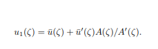
u1(ζ) is a monotonically decreasing function of ζ, and can be calculated from the average interfacial separation ¯u(ζ) and A(ζ) using
 |
| FIG 32 |
The rubber-countersurface apparent contact area is rectangular Lx × Ly. SO “divide” it into
N = Ly/Lx square areas with side L = Lx and area A0 = L ²
 |
| FIG 33 |
The contact region at different magnifications (schematic 34). Note that at the point where the non-contact area (white area) percolate A(ζc) ≈ 0.4A0, while there appear to be complete contact between the surfaces at the lowest magnification ζ = 1: A(1) = A0
 |
| FIG 34 |
A first rough estimate of the leak-rate is obtained by assuming that all the leakage occurs through the critical percolation channel, and that the whole pressure drop
∆P = Pa−Pb
(where Pa and Pb is the pressure to the left and right of the seal) occurs over the critical constriction [of width and length
λc ≈ L/ζc and height
uc = u1(ζc)]
It should assumed laminar flow and that uc << λc, which is always satisfied in practice. Here have introduced a factor α which depends on the exact shape of the critical constriction, but which is expected to be of order unity. Since there are N = Ly/Lx square areas in the rubbercountersurface (apparent) contact area, it get the total leak-rate
Seal Materials Specification