


An Introduction To Clutch Types And Selection
Introduction

Following are the main types of clutches commonly used in engineering practice :
According to the method of transmitting torque:
1. Positive clutches,
semi-centrifugal clutch
The semi-centrifugal clutch uses centrifugal force as well as spring force for keeping it in the engaged position. The figure 8 shows a semi-centrifugal clutch. It consists of levers, clutch springs, pressure plate, Friction lining, flywheel and clutch plate.
Diaphragm clutch
This clutch is similar to the single plate clutch except diaphragm spring is used instead of coil springs for exert pressure on the pressure plate . In the coil springs, one big problem occur that these springs do not distribute the spring force uniformly. To eliminate this problem, diaphragm springs are used into clutches. This clutch is known as diaphragm clutch.
Electro-magnetic clutch
Eddy Current clutch
The torque is transmitted by electromagnetic attraction between the rotating members. Design allows remote control or torque and relative speed


Cork on metal, oiled 0.32
Cork on metal, dry 0.35
Metal on metal, dry 0.15
Disks, metal, oiled 0.10
Asbestos to steel, dry 0.45
Phenolic fiber to cast iron, dry 0.25
Cast iron on brass, dry 0.21


Introduction
A clutch is a machine member used to connect a driving shaft to a driven shaft so that the driven shaft may be started or stopped at will, without stopping the driving shaft. The use of a clutch is mostly found in automobiles. A little consideration will show that in order to change gears
or to stop the vehicle, it is required that the driven shaft should stop, but the engine should continue to run. It is, therefore, necessary that the driven shaft should be disengaged from the driving shaft. The engagement and disengagement of the shafts is obtained by means of a clutch which is operated by a lever.

Types of Clutches
The purpose of a clutch is to initiate motion or increase the velocity of a mass generally by transferring kinetic energy from another moving item. The mass being accelerated is generally a rotating inertial load . Using a friction type clutch the energy is generally transferred using surfaces lined with friction material... Using a positive clutch the energy is transferred using interlocking teeth or projecting lugs. However magnetic force or fluid viscosity is also used to transfer torqueFollowing are the main types of clutches commonly used in engineering practice :
According to the method of transmitting torque:
1. Positive clutches,
2. Friction clutches.
3. Hydraulic clutches.
3. Hydraulic clutches.
 |
| FIG 1 |
According to the method of engaging force:
1. Spring types clutch
2. Centrifugal clutch
2. Centrifugal clutch
3. Semi-centrifugal clutch
4. Electro-magnetic clutch
- They don’t develop no heat during engagement and disengagement because of rigid interlocking of teeth.
- Large torque can be transmitted.
Disadvantages -
- They cannot be engaged at high speed as it can be damaged.
- Some relative motion is required at the start to engage them.
2- Friction Clutches
A friction clutch has its principal application in the transmission of power of shafts and
machines which must be started and stopped frequently. Its application is also found in cases in which
power is to be delivered to machines partially or fully loaded. The force of friction is used to start the
driven shaft from rest and gradually brings it up to the proper speed without excessive slipping of the
friction surfaces. In automobiles, friction clutch is used to connect the engine to the drive shaft. In
operating such a clutch, care should be taken so that the friction surfaces engage easily and gradually
bring the driven shaft up to proper speed. The proper alignment of the bearing must be maintained
and it should be located as close to the clutch as possible. It may be noted that :
1. The contact surfaces should develop a frictional force that may pick up and hold the load with reasonably low pressure between the contact surfaces.
2. The heat of friction should be rapidly dissipated and tendency to grab should be at a minimum.
3. The surfaces should be backed by a material stiff enough to ensure a reasonably uniform distribution of pressure.
Single plate clutch
4. Electro-magnetic clutch
1- Positive Clutches
The positive clutches are used when a positive drive is required. The simplest type of a positive
clutch is a jaw or claw clutch. The jaw clutch permits one shaft to drive another through a direct
contact of interlocking jaws. It consists of two halves, one of which is permanently fastened to the
driving shaft by a sunk key. The other half of the clutch is movable and it is free to slide axially on the driven shaft, but it is prevented from turning relatively to its shaft by means of feather key.
Square jaw type
Square jaw type is used where engagement and disengagement in motion and under load is not necessary. This type of clutch will transmit power in either direction of rotation.
 |
| FIG 2 |
Spiral jaws type
may be left-hand or right-hand, because power transmitted by them is in one direction only. This type
of clutch is occasionally used where the clutch must be engaged and disengaged while in motion.
 |
| FIG 3 |
The use of jaw clutches are frequently applied to sprocket wheels, gears and pulleys. In such a case, the non-sliding part is made integral with the hub.
Some advantages of positive drive clutch are
- No Slip- They don’t develop no heat during engagement and disengagement because of rigid interlocking of teeth.
- Large torque can be transmitted.
Disadvantages -
- They cannot be engaged at high speed as it can be damaged.
- Some relative motion is required at the start to engage them.
2- Friction Clutches
A friction clutch has its principal application in the transmission of power of shafts and
machines which must be started and stopped frequently. Its application is also found in cases in which
power is to be delivered to machines partially or fully loaded. The force of friction is used to start the
driven shaft from rest and gradually brings it up to the proper speed without excessive slipping of the
friction surfaces. In automobiles, friction clutch is used to connect the engine to the drive shaft. In
operating such a clutch, care should be taken so that the friction surfaces engage easily and gradually
bring the driven shaft up to proper speed. The proper alignment of the bearing must be maintained
and it should be located as close to the clutch as possible. It may be noted that :
1. The contact surfaces should develop a frictional force that may pick up and hold the load with reasonably low pressure between the contact surfaces.
2. The heat of friction should be rapidly dissipated and tendency to grab should be at a minimum.
3. The surfaces should be backed by a material stiff enough to ensure a reasonably uniform distribution of pressure.
Single plate clutch
In the single plate clutch (Fig 4) a flywheel is fixed to the engine shaft and a pressure plate is attached to the gear box shaft. This pressure plate is free to move on the spindle of the shaft. A friction plate is situated between the flywheel and pressure plate. Some springs are inserted into compressed position between these plates. When the clutch pedal releases then the pressure plate exerts a force on the friction plate due to spring action. So clutch is in engage position. When the driver pushes the clutch pedal, due to its mechanism, it serves as the disengagement of clutch.
 |
| FIG 4 |
multiple disc clutch
A multiple disc clutch, as shown in Fig. 5, may be used when a large torque is to be transmitted. The inside discs (usually of steel) are fastened to the driven shaft to permit axial motion (except for the last disc). The outside discs (usually of bronze) are held by bolts and are fastened to the housing which is keyed to the driving shaft. The multiple disc clutches are extensively used in motor cars,
machine tools etc.
cone clutch
A cone clutch, as shown in Fig. 6, was extensively used in automobiles, but now-a-days it
has been replaced completely by the disc clutch. It consists of one pair of friction surface only. In a
cone clutch, the driver is keyed to the driving shaft by a sunk key and has an inside conical surface or
face which exactly fits into the outside conical surface of the driven. The driven member resting on
the feather key in the driven shaft, may be shifted along the shaft by a forked lever provided at B, in
order to engage the clutch by bringing the two conical surfaces in contact. Due to the frictional
resistance set up at this contact surface,
The torque is transmitted from one shaft to another. In some cases, a spring is placed around the driven shaft in contact with the hub of the driven. This spring holds the clutch faces in contact and maintains the pressure between them, and the forked lever is used only for disengagement of the clutch. The contact surfaces of the clutch may be metal to metal contact, but more often the driven member is lined with some material like wood, leather, cork or asbestos etc. The material of the clutch faces (i.e. contact surfaces) depends upon the allowable normal pressure and the coefficient of friction.
Centrifugal clutch
machine tools etc.
 |
| FIG 5 |
A cone clutch, as shown in Fig. 6, was extensively used in automobiles, but now-a-days it
has been replaced completely by the disc clutch. It consists of one pair of friction surface only. In a
cone clutch, the driver is keyed to the driving shaft by a sunk key and has an inside conical surface or
face which exactly fits into the outside conical surface of the driven. The driven member resting on
the feather key in the driven shaft, may be shifted along the shaft by a forked lever provided at B, in
order to engage the clutch by bringing the two conical surfaces in contact. Due to the frictional
resistance set up at this contact surface,
The torque is transmitted from one shaft to another. In some cases, a spring is placed around the driven shaft in contact with the hub of the driven. This spring holds the clutch faces in contact and maintains the pressure between them, and the forked lever is used only for disengagement of the clutch. The contact surfaces of the clutch may be metal to metal contact, but more often the driven member is lined with some material like wood, leather, cork or asbestos etc. The material of the clutch faces (i.e. contact surfaces) depends upon the allowable normal pressure and the coefficient of friction.
 |
| FIG 6 |
Centrifugal clutch
The centrifugal clutches are usually incorporated into the motor pulleys. It consists of a number of shoes on the inside of a rim of the pulley, as shown in Fig. 7. The outer surface of the shoes are covered with a friction material. These shoes, which can move radially in guides, are held against the boss (or spider) on the driving shaft by means of springs. The springs exert a radially inward force which is assumed constant.
The weight of the shoe, when revolving causes it to exert a radially outward force (i.e. centrifugal force). The magnitude of this centrifugal force depends upon the speed at which the shoe is revolving.
A little consideration will show that when the centrifugal force is less than the spring force, the shoe remains in the same position as when the driving shaft was stationary, but when the centrifugal force is equal to the spring force, the shoe is just floating. When the centrifugal force exceeds the spring force, the shoe moves outward and comes into contact with the driven member and presses against it. The force with which the shoe presses against the driven member is the difference of the centrifugal force and the spring force. The increase of speed causes the shoe to press harder and enables more torque to be transmitted.
 |
| FIG 7 |
The semi-centrifugal clutch uses centrifugal force as well as spring force for keeping it in the engaged position. The figure 8 shows a semi-centrifugal clutch. It consists of levers, clutch springs, pressure plate, Friction lining, flywheel and clutch plate.
A semi-centrifugal clutch has levers and clutch springs which are arranged equally on the pressure plate. The springs of the clutch are designed to transmit the torque at normal engine speed. While the centrifugal force helps in torque transmission at higher engine speed.
At normal engine speeds, when the power transmission is low, the springs keep the clutch engaged, the weighted levers do not have any pressure on the pressure plate.
At high engine speed when the power transmission is high, the weights fly off and the levers also exert pressure on the plate, keeping the clutch firmly engaged.
This types of clutches consist of less stiff springs, so that the driver may not get any strain while operating the clutch. When vehicle speed decreases the weights fall and the lever does not apply any pressure on the pressure plate.
Only the spring pressure is applied to the pressure plate which is enough to keep the clutch engaged. An adjusting screw is fitted at the end of the lever, by means of which the centrifugal force on the pressure plate can be adjusted.
 |
| FIG 8 |
Diaphragm clutch
This clutch is similar to the single plate clutch except diaphragm spring is used instead of coil springs for exert pressure on the pressure plate . In the coil springs, one big problem occur that these springs do not distribute the spring force uniformly. To eliminate this problem, diaphragm springs are used into clutches. This clutch is known as diaphragm clutch.
 |
| FIG 9 |
In this type of clutch, the flywheel consists of winding.The current supplied in the winding from the battery or dynamo. When the current passes through the winding, it produces an electromagnetic field which attracts the pressure plate, thereby engaging the clutch. When the supply is cut-off, the clutch is disengaged.
 |
| FIG 10 |
Vacuum Clutch
It consists of a vacuum cylinder with piston, solenoid operate valve, reservoir and a non- return valve. The reservoir is connected to the engine manifold through a non-return valve. Vacuum cylinder is connected to the reservoir through solenoid operated valve. The solenoid is operated form the battery and the circuit incorporates a switch which is placed in the gear lever.
Movement of the piston is transmitted by a linkage to the clutch, causing it to disengage. When the driver is not operating the gear lever, the switch is open and the clutch remains engaged due to the force of springs.
 |
| FIG 11 |
Eddy Current clutch
The torque is transmitted by electromagnetic attraction between the rotating members. Design allows remote control or torque and relative speed
 |
| FIG 12 |
3- Hydraulic clutch
Fluid coupling
It is a hydraulic unit that replaces a clutch in a semi or fully automatic clutch. In this type of clutch, there is no mechanical connection between driving member and driven member. A pump impeller is blotted on a driving member (Engine) and a turbine runner is bolted on the driven member (Gearbox). Both the above unit is enclosed into single housing filled with a liquid.
This liquid serve as the torque transmitter from the impeller to the turbine. When the driving member starts rotating then the impeller also rotates and through the liquid outward by centrifugal action. This liquid then enters the turbine runner and exerts a force on the runner blade. This make the runner as well as the driven member rotate. The liquid flows to the runner then flows back into the pump impeller, thus complete the circuit. It is not possible to disconnect to the driving member to the driven member when the engine is running. So the fluid coupling is not suitable for ordinary gear box. It is used with automatic or semi-automatic gear box.
Hydraulic torque converter
The Uses of Clutches
Clutches are rotary mechanical power transmission elements. There many uses and applications are:
--Clutches are used to engage and disengage the transmission of rotary mechanical power from one system element to another. This allows the driven part of the system to be turned on and off by controlling its power supply.
--Clutches are used to control the power from one system element to another. This avoids shock loads and damage to the driven parts.
--Clutches are used to disengage the drive from the driven parts. This allows the drive to be started under `no-load' conditions, which allows the drive to be operated at its rated conditions when the driven parts are connected to it. The system will be cost efficient because it will be started by a well matched drive.
--Clutches are used as over-running devices. An over-running clutch allows the drive to transmit torque to the driven machine in one direction only. Considering the relative velocities of the drive and driven shafts, relative motion of the drive shaft and driven shaft is permitted with the drive rotating in one direction, but not in the other.
--Clutches are used as torque limiting devices. A torque limiting clutch responds to the torque difference across the clutch. At a predefined torque difference, it will completely disengage the two components connected, or will allow a predefined amount of torque to be transmitted, dissipating the excess energy.
This clutch uses hydraulic fluid to transmit the torque. According to their design, this clutch is subdivided into two types.
Fluid coupling
It is a hydraulic unit that replaces a clutch in a semi or fully automatic clutch. In this type of clutch, there is no mechanical connection between driving member and driven member. A pump impeller is blotted on a driving member (Engine) and a turbine runner is bolted on the driven member (Gearbox). Both the above unit is enclosed into single housing filled with a liquid.
This liquid serve as the torque transmitter from the impeller to the turbine. When the driving member starts rotating then the impeller also rotates and through the liquid outward by centrifugal action. This liquid then enters the turbine runner and exerts a force on the runner blade. This make the runner as well as the driven member rotate. The liquid flows to the runner then flows back into the pump impeller, thus complete the circuit. It is not possible to disconnect to the driving member to the driven member when the engine is running. So the fluid coupling is not suitable for ordinary gear box. It is used with automatic or semi-automatic gear box.
 | |
| FIG 13 |
Hydraulic torque converter is same as the electric transformer. The main purpose of the torque converter is to engage the driving member to driven member and increase the torque of driven member. In the torque converter, an impeller is bolted on the driving member, a turbine is bolted on the driven member and a stationary guide vanes are placed between these two members. This all parts are enclosed into single housing which filled with hydraulic liquid. The impeller rotates with the driven member and it through the liquid outward by centrifugal action. This liquid flowing from the impeller to turbine runner exerts a torque on the stationary guide vanes which changes the direction of liquid, thereby making possible the transformation of torque and speed. The difference of torque between impeller and turbine depends upon these stationary guide vanes. The hydraulic torque converter serves the function of clutch as well as the automatic gear box.
 |
| FIG 14 |
Clutches are rotary mechanical power transmission elements. There many uses and applications are:
--Clutches are used to engage and disengage the transmission of rotary mechanical power from one system element to another. This allows the driven part of the system to be turned on and off by controlling its power supply.
--Clutches are used to control the power from one system element to another. This avoids shock loads and damage to the driven parts.
--Clutches are used to disengage the drive from the driven parts. This allows the drive to be started under `no-load' conditions, which allows the drive to be operated at its rated conditions when the driven parts are connected to it. The system will be cost efficient because it will be started by a well matched drive.
--Clutches are used as over-running devices. An over-running clutch allows the drive to transmit torque to the driven machine in one direction only. Considering the relative velocities of the drive and driven shafts, relative motion of the drive shaft and driven shaft is permitted with the drive rotating in one direction, but not in the other.
--Clutches are used as torque limiting devices. A torque limiting clutch responds to the torque difference across the clutch. At a predefined torque difference, it will completely disengage the two components connected, or will allow a predefined amount of torque to be transmitted, dissipating the excess energy.

Considerations in Designing a Friction Clutch
The following considerations must be kept in mind while designing a friction clutch.
1. The suitable material forming the contact surfaces should be selected.
2. The moving parts of the clutch should have low weight in order to minimise the inertia load,
especially in high speed service.
3. The clutch should not require any external force to maintain contact of the friction surfaces.
4. The provision for taking up wear of the contact surfaces must be provided.
5. The clutch should have provision for facilitating repairs.
6. The clutch should have provision for carrying away the heat generated at the contact surfaces.
7. The projecting parts of the clutch should be covered by guard.
Material for Friction Surfaces
The material used for lining of friction surfaces of a clutch should have the following characteristics :
1. It should have a high and uniform coefficient of friction.
2. It should not be affected by moisture and oil.
3. It should have the ability to withstand high temperatures caused by slippage.
4. It should have high heat conductivity.
5. It should have high resistance to wear and scoring.
The materials commonly used for lining of friction surfaces and their important properties are
shown in the following table.
Clutches desgin
Power Transmitted by Disk Clutches

where
μ = coefficient of friction (static)
Rm = mean radius of engaged frictional surfaces, in
F = axial force holding the disks in contact, lb
n = number of frictional surfaces
S = speed of drive shaft, rpm
Values for the coefficient of static friction (μ) are as follows:Cork on metal, oiled 0.32
Cork on metal, dry 0.35
Metal on metal, dry 0.15
Disks, metal, oiled 0.10
Asbestos to steel, dry 0.45
Phenolic fiber to cast iron, dry 0.25
Cast iron on brass, dry 0.21
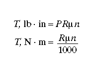
Slipping Torque. Single-plate clutch-slipping torque is given as

and spring pressure or actuating force as

where
T = torque capacity, lb ⋅ in or N ⋅ m
μ = coefficient of static friction
P = spring pressure or actuating force, lb or N
R = effective friction radius, in or mm
n = number of frictional surfaces
Proportions of Disk Linings. The average radius or effective frictional radius is

where
R = effective frictional radius, in or mm
do = outside diameter of disk lining, in or mm
di = inside diameter of disk lining, in or mm
Slipping-Torque Capacities (Plate Clutches). The slipping-torque capacity of a friction
plate clutch is the amount of torque the clutch is capable of transmitting when the clutch is
just in the process of slipping.
In order to prevent slipping in service, a safety factor or multiplier must be applied to the
slipping-torque capacity of the clutch. This factor or multiplier should be kept from 1.40 to
1.60 above the maximum torque of the driving element or motor supplying torque through
the clutch.
Example. If you wish to transmit 2500 lb ⋅ in of torque through the clutch, the clutch
should be designed so that its slipping-torque capacity is ≈1.50 × 2500 = 3750 lb . in. Use the
preceding equations shown to do the simple calculations.
Spring Pressure or Actuating Force. The clutch spring pressure or actuating force should be
applied so that the pressure on the clutch disk material is kept at 20 to 35 psi when the clutch
is engaged (automotive-type clutches). For allowable pressures of other clutch materials, see
table

When the horsepower to be transmitted and the rpm of the shaft are given

where
Mt = torque of shaft, lb in
hp = horsepower
n = rpm of shaft
S = spring pressure or axial force, lb
r = mean radius of cone, in
μ = coefficient of static friction
Q = total force normal to conical surface, lb
b = width of cone section, in
P = tangential force at rim of cone, lb
α = half cone angle, degrees
ρ = pressure normal to cone surface, psi


In this post every detail is useful and effective. It is my pleasure to be here. Thanks for share with us.
ReplyDeleteB series trans rebuild parts
Thanks for sharing this informative post. I was really looking forward to such blog.
ReplyDelete90mm throttlebody