

An Introduction To Worm Gearing
Introduction
The worm pair or worm gearbox is a type of gearbox whose axis passes, most often at an angle of 90o
. The worm gear unit consists of a worm gear and a worm shown in Figure 1
 |
| FIG 1 |
Worm Gearing Classification
Worm gearing may be divided into two general classes:
- fine-pitch worm gearing,
- coarse-pitch worm gearing
 |
| FIG 2 |
Fine-pitch worm gearing is segregated from coarse-pitch worm gearing for the following reasons ;
1) Fine-pitch worms and worm gears are used largely to transmit motion rather than power. Tooth strength except at the coarser end of the fine-pitch range is seldom an important factor; durability and accuracy, as they affect the transmission of uniform angular motion, are of greater importance
2) Housing constructions and lubricating methods are, in general, quite different for fine pitch-
worm gearing
3) Because fine-pitch worms and wormgears are so small, profile deviations and tooth bearings cannot be measured with the same accuracy as can those of coarse pitches.
4) Equipment generally available for cutting fine-pitch wormgears has restrictions which limit the diameter, the lead range, the degree of accuracy attainable, and the kind of tooth bearing obtainable.
5) Special consideration must be given to top lands in fine-pitch hardened worms and wormgear- cutting tools.
6) Interchangeability and high production are important factors in fine-pitch worm gearing; individual matching of the worm to the gear, as often practiced with coarse-pitch precision worms, is impractical in the case of fine-pitch worm drives.
 t.
t.
Worm Gear Work Principle
The worm (screw) continuously rotates and drives the worm wheel (meshed with it). Worm and worm gear form a lower pair as they have sliding contact with each other.
In a worm gear drive, power is always transmitted from worm to worm wheel. Power cannot be transmitted from worm wheel to worm. This phenomenon is called self-locking. It is highly useful in many applications.
Velocity ratio is determined by the number of teeth on worm gear and the number starts on worm. Power transmission decreases with increase in velocity ratio.
Note: A screw (worm) is said to have one start if it advances one groove (in linear direction), in one complete revolution. It is said to have have two starts if it advances two grooves (in linear direction) in one revolution. The worm shown in the animation above has four starts.
 |
| FIG 3 |
Applications of Worm Gear Drives
 |
| FIG 4 |
Worm drives are used in:
1- Gate control mechanisms
2- Hoisting machines
3- Automobile steering mechanisms
4- Lifts
5- Conveyors
6- Presses
Worm Gear Types
There are three different types of gears (figure 5) that can be used in a worm drive.
1- non-throated worm gears. These don't have a throat, or groove, machined around the circumference of either the worm or worm wheel.
2- single-throated worm gears, in which the worm wheel is throated.
3- double-throated worm gears, which have both gears throated. This type of gearing can support the highest loading.
 |
| FIG 5 |
An enveloping (hourglass) worm has one or more teeth and increases in diameter from its middle portion toward both ends.
Double-enveloping wormgearing comprises enveloping worms mated with fully enveloping wormgears. It is also known as globoidal wormgearing.
1- non-throated worm gear
The non-throated worm gear is a straight worm that doesn’t comprise of a grooved mechanism.
The non-throated worm gear is a straight worm that doesn’t comprise of a grooved mechanism.
2- Single-thread Worms Gears.
A single-throated worm is involved concave helical teeth being wrapped around the worm.The ratio of the worm speed to the wormgear speed may range from 1.5 or even less up to 100 or more. Worm gearing having high ratios are not very efficient as transmitters of power; nevertheless high as well as low ratios often are required. Since the ratio equals the number of wormgear teeth divided by the number of threads or “starts” on the worm, single-thread worms are used to obtain a high ratio. As a general rule, a ratio of 50 is about the maximum recommended for a single worm and
wormgear combination, although ratios up to 100 or higher are possible. When a high ratio is required, it may be preferable to use, in combination, two sets of worm gearing of the multi-thread type in preference to one set of the single-thread type in order to obtain the same total reduction and a higher combined efficiency.
Single-thread worms are comparatively inefficient because of the effect of the low lead angle; consequently, single-thread worms are not used when the primary purpose is to transmit power as efficiently as possible but they may be employed either when a large speed reduction with one set of gearing is necessary, or possibly as a means of adjustment, especially if “mechanical advantage” or self-locking are important factors.
3- Multi-thread Worm Gears.
The double-throated worm gear has concave teeth on both the gear itself and the worm screw.When worm gearing is designed primarily for transmitting power efficiently, the lead angle of the worm should be as high as is consistent with other requirements and preferably between, say, 25 or 30 and 45 degrees. This means that the worm must be multi-threaded. To obtain a given ratio, some number of wormgear teeth divided by some number of worm threads must equal the ratio. Thus, if the ratio is 6, combinations such as the following might be used: 24/4 , 30/5 , 36/6 , 42/7
The numerators represent the number of wormgear teeth and the denominators, the number of worm threads or “starts.” The number of wormgear teeth may not be an exact multiple of the number of threads on a multi-thread worm in order to obtain a “hunting tooth” action.
Explanation of Hand
The purpose of left- and righi-hand gearing
is to cbange the relative rotation ofthe worm to
the gear. Hand refers to the direction of axial
thread movement as the worm is rotated. Ifyou
point your thumb in the direction of ax ial movement and curl your fingers in the direction of rotation, the hand that corresponds to the worm
is the hand of the gear set. (Figure 6)
Bolts are a simple example. Normally they are
right. handed, and experimenting with a nut and
bolt win help to clarify this description.
Right-hand gear sets, like bolts, are the
industry standard. More right-hand gear ratios
are available as standard items, and most manufacturers win supply right-hand gearing unless
otherwise pecified, This does not mean there
is a flaw in left-hand gearing, but left-hand
ratios may not be as readily available.
 |
| FIG 6 |
Dimension Specifications
Gears mate via teeth with very specific geometry. Pitch is a measure of tooth spacing and is expressed in several ways.
Diametral pitch (DP) is the ratio of the number of teeth to the pitch diameter of a gear; a higher DP therefore indicates finer tooth spacing. It is easily calculated by the formula DP= (N+2) ÷ OD, where N is the number of teeth, and OD represents the circumferential measurement.
Circular pitch (CP) is a direct measurement of the distance from one tooth center to the adjacent tooth center. In a worm drive, it is called axial pitch and can be measured by the formula CP= Π ÷ DP.
Module (M) is a typical gear discipline and is a measurement of the size and teeth number of the gear. Gears measured in inches earn 'English module' distinction to prevent confusion. M = OD ÷ N
Pressure angle is the angle of tooth drive action, or the angle between the line of force between meshing teeth and the tangent to the pitch circle at the point of mesh. Typical pressure angles are 14.5° or 20°.
Lead angle is the angle at which the gear teeth are aligned compared to the axis. This is also the point of contact between the drive and the gear. This is also known as helix angle.
 |
| FIG 7 |
Tooth Form of Worm and WormgearThe shape of the worm thread in the normal plane is defined as that which is produced by a symmetrical double-conical cutter or grinding wheel having straight elements and an included angle of 40 degrees. Because worms and wormgears are closely related to their method of manufacture, it is
impossible to specify clearly the tooth form of the wormgear without referring to the mating worm. For this reason, worm specifications should include the method of manufacture and the diameter of cutter or grinding wheel used. Similarly, for determining the shape of the generating tool, information about the method of producing the worm threads must be given to the manufacturer if the tools are to be designed correctly.
The worm profile will be a curve that departs from a straight line by varying amounts, depending on the worm diameter, lead angle, and the cutter or grinding wheel diameter. A method for calculating this deviation is given in the Standard. The tooth form of the worm gear is understood to be made fully conjugate to the mating worm thread.

FIG 8
Materials for Worm Gearing.
Worm gearing, especially for power transmission, should have steel worms and phosphor bronze wormgears. This combination is used extensively. The worms should be hardened and ground to obtain accuracy and a smooth finish.
The phosphor bronze wormgears should contain from 10 to 12 per cent of tin. The S.A.E.
phosphor gear bronze (No. 65) contains 88–90% copper, 10–12% tin, 0.50% lead, 0.50%
zinc (but with a maximum total lead, zinc and nickel content of 1.0 per cent), phosphorous
0.10–0.30%, aluminum 0.005%. The S.A.E. nickel phosphor gear bronze (No. 65 + Ni)
contains 87% copper, 11% tin, 2% nickel and 0.2% phosphorous.
Number of Threads or “Starts” on Worm: The number of threads on the worm ordinarily varies from one to six or eight, depending upon the ratio of the gearing. As the ratio is increased, the number of worm threads is reduced, as a general rule. In some cases, however, the higher of two ratios may also have a larger number of threads. For example, a ratio of 61⁄5 would have 5 threads whereas a ratio of 65⁄6 would have 6 threads. Whenever the ratio is fractional, the number of threads on the worm equals the denominator of the fractional part of the ratio
worm gear boxes calcs
The ratio of output and input power is efficiency of gearboxes. Compared to other types of gearboxes, the worm gearbox has a lower value of the efficiency. The reason for the difference between the input and the output power is the power losses occurring in the gearbox. The efficiency of the worm gearbox is determined as the ratio of the output power to the input

where :
P ul - input power [W],
Pizl - output power [W],
PG - total losses of power [W]
From the previous expression, it can be concluded that the output power is equal to the difference in the input power and the power lost to various types of resistance, which is mostly converted into heat. The degree of loss is the relationship between the power that is lost and the input power, and it can be concluded from the previous expression that if this ratio is lower the efficiency is higher and vice versa. If P1 is power applied on worm, and P2 is power applied on worm gear, in the case where the worm is drive element, the efficiency can be expressed as
- In case where worm is drive element:

In case where worm gear is drive element:

Power losses in worm gearbox
The total power losses occurring in the worm gearbox consist of the loss of power due to the slip
resistance of the worm pair during movement PGz , the power loss occurring in the bearings PGL and
the loss of power during idling PG0
. So the total power losses can be determined as

The loss of power due to the slip resistance of the worm pair during movement, can be determined as

where are:
FN
- normal force on the side of the tooth [N],
µz
- coefficient of friction of worm gear
pair,
ν k
- sliding speed [m/s],which can be determined by the following expression
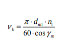
where:
dm1 - is middle circle diameter [m],
n1 - is rpm of worm[ min−¹ ],
γm - is an angle of inclination
of the coil.
The loss of power during idling can be determined by the following expression

where:
a - is a distance between the axes [mm],
n 1- is rpm of warm[ min− ¹],
ν 40 - is a kinematic
viscosity of oil on 40o
[ mm² /s ].
The power loss occurring in the bearings can be determined by the following expression :
if roller bearings are embedded on the shafts of worm and worm gear

if sliding bearings are embedded on the shafts of worm and worm gear

worm gear formulas

Advantages of Worm Drives:
Worm gear drives operate silently and smoothly.
They are self-locking.
They occupy less space.
They have good meshing effectiveness.
They can be used for reducing speed and increasing torque.
High velocity ratio of the order of 100 can be obtained in a single step.
Disadvantages of Worm Drives:
Worm gear materials are expensive.
Worm drives have high power losses and low transmission efficiency.
They produce a lot of heat.


This blog highly plagiarized my work and that of others. Straight copy of text and even took a figure from my article.
ReplyDelete