

An Introduction To Springs Types And Formulas
Introduction
A spring is an elastic object used to store mechanical energy. Springs are elastic bodies (generally metal) that can be twisted, pulled, or stretched by some force. They can return to their
original shape when the force is released. In other words it is also termed as a resilient member.
A spring is a flexible element used to exert a force or a torque and, at the same time, to store
energy.
The force can be a linear push or pull, or it can be radial, acting similarly to a rubber band around
a roll of drawings.
The torque can be used to cause a rotation, for example, to close a door on a cabinet or to provide
a counterbalance force for a machine element pivoting on a hinge.

Spring Work Princiciple
F=-k*𝛥
where
(F) represents the force generated by the spring,
(Δx) represents the displacement or the amount of deformation from the spring’s relaxed or neutral position,
(k) is a parameter that is known as the spring constant.
The negative sign in the above expression reflects the directionality of the resulting force from the displacement of the spring. If you pull a spring apart (increase its length), the force that results will be in the opposite direction to the action you took (tending to return the spring back to its neutral position). Similarly, if you push on a string to reduce its length, the force that results will be in the opposite direction and will attempt to increase the spring’s length and return it to its neutral position.
The spring constant k is a function not only of the material used for manufacturing the spring but also is determined by several factors that relate to the geometry of the spring design. Those design factors include:
1- The wire diameter of the spring material.
2- The coil diameter, which is a measure of the tightness of the spring
3- The free length of the spring, which represents its length when it is not attached to anything and is not undergoing displacement from equilibrium.
4- The number of active coils contained in the spring, which means the number of coils that can expand and contract in normal use.
The unit of measure for the spring constant is a force unit divided by a length unit. In the metric system of measurement, this would be a Newton/meter, or Newton/centimeter, for example
Spring Classification
Springs can be classified according to the direction and the nature of the force exerted by
the spring when it is deflected.
1- Push Springs :
a-Helical compression spring,
b- Belleville spring,
c-Torsion spring,
d- force acting spring
e- flat spring, such as a cantilever spring or leaf spring
2- Pull Springs :
a- Helical extension spring,
b- Torsion spring,
c- force acting at the end of torque arm.
d- Flat spring, such as a cantilever spring or leaf spring,
e- Draw bar spring (special case of the compression spring)
f- constant – force spring.
3- Radial torque springs :
a- Garter spring,
b- elastomeric band,
c- spring clamp,
d- Torsion spring,
e- Power spring
There are a variety of spring types available, the selection of which depends on the force or torque needed by the application and the operational conditions. The most common spring types include:1 - Compression Springs
2 - Extension Springs
3- Torsion Springs
4 - Constant Force Springs
5 - Belleville Springs
6 - Drawbar Springs
7 - Volute Springs
8 - Garter Springs
9 - Flat Springs
10 - Gas Springs
11 - Air Springs
Common Spring Types
4 - Constant Force Springs
5 - Belleville Springs
6 - Drawbar Springs
7 - Volute Springs
8 - Garter Springs
9 - Flat Springs
10 - Gas Springs
11 - Air Springs
Common Spring Types
1- Compression Springs:
2- Tension Springs:
Tension springs have an initial length and get longer when a force is applied. An example of
relaxed and an extended tension spring is shown in Figure 2. Tension springs are also found in a
wide range of sizes and strengths. From tiny springs found in mechanical watches, to large
tension springs used to lift garage doors. The spring constant of a tension spring defines the
amount of the increase in the length that the spring undergoes under a certain load. The
boundary between the elastic and permanent deformation creates a limit for the maximum load
that can be applied to a tension spring.
Torsion springs, however, deform around an axis of rotation.
Helical cylindrical compression springs
Springs of cylindrical shape made of helically coiled wires, with constant clearance between the active coils, able to absorb external counter-acting forces applied against each other in their axis. Springs with wire diameter up to approx. 16 mm are usually cold wound. Hot forming shall be used for the production of heavily loaded springs of greater sizes with a diameter of the over 10 mm. Compression springs are usually made of wires and rods of round section. Springs of rectangular wire are most often used in applications where low constructional height of the spring (springs with b>h) is required together with relatively high load.
Specific properties
- suitable for low and medium load forces
- linear working characteristics
- relatively low spring constant
- easy mounting and dismantling
- low production costs
Springs are classified by the mode in which they deform under an applied force. Compression
springs have an initial length and get shorter when a force is applied. An example of a compression spring is shown in Figure 1. Compression springs are found in a wide range of sizes and strengths. From tiny, light duty springs found in a lock barrel, to large, heavy-duty
shock absorber springs in an automobile. The spring constant of a compression spring defines
the amount of the decrease in the length that the spring undergoes under a certain load. Two
things can limit the deformation of a compression spring. First, if the compression spring is
deformed such that the wire rings are in contact, the compression spring has reached a maximum
applied force. Second, if the compression spring permanently deforms prior to reaching the fully
compressed state previously described, the maximum applicable force occurs just before
permanent deformation.
 |
| FIG 1 |
Tension springs have an initial length and get longer when a force is applied. An example of
relaxed and an extended tension spring is shown in Figure 2. Tension springs are also found in a
wide range of sizes and strengths. From tiny springs found in mechanical watches, to large
tension springs used to lift garage doors. The spring constant of a tension spring defines the
amount of the increase in the length that the spring undergoes under a certain load. The
boundary between the elastic and permanent deformation creates a limit for the maximum load
that can be applied to a tension spring.
 |
| FIG 2 |
3- Torsion Springs:
Torsion springs do move linearly like the compression and tension springs previously mentioned.Torsion springs, however, deform around an axis of rotation.
 |
| FIG 3 |
Springs of cylindrical shape made of helically coiled wires, with constant clearance between the active coils, able to absorb external counter-acting forces applied against each other in their axis. Springs with wire diameter up to approx. 16 mm are usually cold wound. Hot forming shall be used for the production of heavily loaded springs of greater sizes with a diameter of the over 10 mm. Compression springs are usually made of wires and rods of round section. Springs of rectangular wire are most often used in applications where low constructional height of the spring (springs with b>h) is required together with relatively high load.
Specific properties
- suitable for low and medium load forces
- linear working characteristics
- relatively low spring constant
- easy mounting and dismantling
- low production costs
 |
| FIG 4 |
Types of Ends.
Four basic types of ends are used: closed (squared) ends, closed (squared) ends ground, plain ends, and plain ends ground. Figure 6.6 illustrates the various end conditions. Closed and ground springs are normally supplied with a ground bearing surface of 270 to 330°.
Helical conical compression springsFour basic types of ends are used: closed (squared) ends, closed (squared) ends ground, plain ends, and plain ends ground. Figure 6.6 illustrates the various end conditions. Closed and ground springs are normally supplied with a ground bearing surface of 270 to 330°.
 |
| FIG 5 |
Springs of conical shape made of helically coiled wires, with constant clearance between the active coils, able to absorb external counter-acting forces applied against each other in their axis. Springs with wire diameter up to approx. 16 mm are usually cold wound. Hot forming shall be used for the production of heavily loaded springs of greater sizes with a diameter of the over 10 mm. Conical springs are usually used if the spring constant is to rise together with its progressing compression.
Specific properties
- suitable for low and medium load forces
- nonlinear (progressive) working characteristics
- relatively low spring constant
- easy mounting and dismantling
- low production costs
 |
| FIG 6 |
Belleville springs
Annular rings of hollow truncated cone, able to absorb external axial forces counter-acting against each other. The spring section is usually rectangular. Springs of larger sizes (t > 6 mm) are sometimes made with machined contact flats.
Belleville springs are designed for higher loads with low deformations. They are used individually or in sets. When using springs in a set it is necessary to take account of friction effects. Friction in the set accounts for 3 – 5% of loading per each layer. Working load must then be increased by this force.
Stress occurring in the Belleville spring is rather complex. Maximum stress (compressive) develops in the inner top edge. Tensile stress occurs on the bottom outer edge. Maximum compressive stress serves for strength check of springs subjected to static load. In the springs subjected to cyclic (fatigue) load the pattern of tensile stresses is checked.
Specific properties
- suitable for large loading forces
- nonlinear (degressive) working characteristics
- high spring constant (stiffness)
- low space requirements
- easy mounting and dismantling
- low production costs
 |
| FIG 7 |
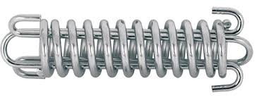
Helical cylindrical tension springs
Springs of cylindrical shape made of helically coiled wires, with constant clearance between the active coils, able to absorb external axial forces counter-acting from each other. Springs with wire diameter up to approx. 16 mm are usually cold wound. Hot forming shall be used for the production of heavily loaded springs of greater sizes with a diameter of the over 10 mm. Tension springs are usually made of wires and rods of round section. Springs made of rectangular wire are used very rarely.
With regards to the considerable effects of the shape and design of fixing eyes on reduction of the spring's service life and impossibility of perfect shot peening of the spring, it is not advisable to use tension springs exposed to fatigue loading. If it is necessary to use a tension spring with fatigue loading, it is advisable to avoid use of fixing eyes and choose another type of fixing of the spring.
Specific properties
- suitable for low and medium load forces
- less suitable for cyclic (fatigue) load
- linear working characteristics
- relatively low spring constant
- easy mounting and dismantling
- low production costs
 |
| FIG 8 |
Design of spring ends
Tension springs are used in many different designs. The most common spring ends can be found in the following picture. The type of design of the spring ends depends on the desired method of fixing the spring, its dimensions and the amount of loading.
 |
| FIG 9 |
Leaf springs
Springs based on the principle of long slander beams of rectangular section subjected to bending. They are used as cantilever springs (fixed at one end), or as simple beams (fixed at both ends). The leaf springs can be used either independently or in sets (laminated leaf springs).
Specific properties
Single springs
- suitable for low and medium load forces
- linear working characteristics
- relatively low spring constant
- considerable length requirements, otherwise minimum space needed
- low production costs
Laminated leaf springs
- suitable for higher loading forces
- theoretically linear working characteristics (friction between the leaves causes hysteretic pattern of the working curve)
- relatively higher spring constant (stiffness)
- high space requirements
- demanding maintenance (lubrication and cleanness)
 |
| FIG 10 |
Torsion bar springs
Springs based on the principle of long slender bars of circular or rectangular section subjected to torsion. The ends of bars with circular section are mostly fixed by means of grooving. Sometimes one end is square-shaped in order to facilitate attachment. Torsion bar springs must be secured against bending stress.
Specific properties
- suitable for higher loading torques
- linear working characteristics
- high spring constant
- considerable length requirements, otherwise minimum space needed
- low production costs
 |
| FIG 11 |
Drawbar Springs
Drawbar springs are coil compression springs incorporating U-shaped wire forms inserted for use in extension applications. The drawbar spring combines the tension application of the extension spring with the positive stop feature of the compression spring. Key specifications include the free length, maximum spring deflection, and wire diameter. Drawbar springs are used primarily in applications where a tension-producing spring is required where the self-limiting feature of compression springs is also needed. A typical use for a drawbar spring is supporting porch swings where the spring cannot be loaded past the point of failure due to the self-limiting property of the compression spring.
 |
| FIG 12 |
Spiral springs
The spring made of a strip with rectangular section wound into the shape of Archimedes spiral, with constant spacing between its active coils, loaded with torque in the direction of the winding.
Specific properties
- suitable for low loading torques
- linear working characteristics
- low spring constant
- low production costs
 |
| FIG 13 |
Helical cylindrical torsion springs
Springs of cylindrical shape made of helically coiled wires, with constant spacing between the active coils, able to absorb external forces applied in the planes perpendicular to the winding axis through a torque in the direction of winding or unwinding. Springs with wire diameter up to approx. 16 mm are usually cold wound. Hot forming shall be used for the production of heavily loaded springs of greater sizes with a diameter of the over 10 mm.
Specific properties
- suitable for low and medium loading torques
- linear working characteristics
- relatively low spring constant
- low production costs
 |
| FIG 14 |
Volute Springs
Volute springs are flat metal strips wound together to form helical spirals that are typically used in compression applications. Key specifications include the intended application, diameter, stroke, material, and the end attachment style. Volute springs are used primarily in applications where a compression spring is required having a long fatigue life or high spring force repeatability. They come in a variety of sizes depending on the application and force required, and materials. Some volute springs are single-ended while others are double. An easily recognizable use of the volute spring is the compression spring found in high-quality nail clippers or pruning shears.
 |
| FIG 15 |
Garter Springs
Garter springs are spring coils whose ends are joined to form circular springs which are used to provide a radial force in components that may contain a variable load. A common use of garter springs is in hydraulic, pneumatic, and radial shaft seals where they provide a slight inward force on sealing lips.
 |
| FIG 16 |
Gas Springs
Gas springs are mechanical devices, consisting of a cylinder and a rod, that use the pressure from a pre-charge of nitrogen, or other inert gases, to produce a force bias on a piston or rod. Key specifications include the intended application, stroke, compressed length, extended length, force, as well as the features. Gas Springs are used primarily in the automobile industry for the raising and/or lowering of hoods or hatches. They are available in a variety of sizes and stroke length depending on the application and load requirements. Other applications include use on office chairs for seat height adjustments.
 |
| FIG 17 |
Air Springs
Air springs are air pressurized bellow or bladder type devices of a variety of shapes and sizes and used for providing actuation, shock absorption, and vibration isolation. Key specifications include the intended application, type, style, physical dimensions, mounting type, as well as the features. Air springs are used primarily in machine applications such as vehicle suspensions for shock absorption and as machine mounts for vibration isolation. They are available in a variety of types and sizes based on the load requirements and application. Other uses include lifting, compressing, tilting, etc. Air springs used for vibration isolation are also known as air cushions.
 |
| FIG 18 |
Hydraulic springs
Hydraulic springs are comparatively small, thick-walled cylinders in which the spring effect is produced by applying a load to the fluid in the cylinder through a small piston entering at the centre of one end of the cylinder. The piston movement, or deflection, is produced by the compression of the fluid and the deformation (bulging) of the cylinder walls. These springs are particularly useful in applications requiring high load capacities and stiffnesses.
 |
| FIG 19 |
SELECTION OF SPRING MATERIALS
Springs are resilient structures designed to undergo large deflections within their elastic range. It follows that the materials used in springs must have an extensive elastic range.
Some materials are well known as spring materials. Although they are not specifically designed alloys, they do have the elastic range required. In steels, the mediumand high-carbon grades are suitable for springs. Beryllium copper and phosphor bronze are used when a copper-base alloy is required. The high-nickel alloys are used when high strength must be maintained in an elevated-temperature environment.
The selection of material is always a cost-benefit decision. Some factors to be considered are :
- costs,
- availability,
- formability,
- fatigue strength,
- corrosion resistance,
- stress relaxation,
- electric conductivity.
The right selection is usually a compromise among these factors. Table 1 lists some of the more commonly used metal alloys and includes data which are useful in material selection.
Surface quality has a major influence on fatigue strength. This surface quality is a function of the control of the material manufacturing process. Materials with high surface integrity cost more than commercial grades but must be used for fatigue applications, particularly in the high cycle region.
 |
| TABLE 1 |
Springs Applications
Compression springs are exceptionally common. They are active in combustion engines, stamping presses, cellular phones, electronics and hand tools. Compression springs can also be used for vibration insulation such as in a suspension. One of the most overlooked employments of this type of spring is in ball point pens, while the working mechanism of a mattress box spring is widely recognized as a compression spring.
Extension springs are common in trampolines, screen and storm doors, garage doors, toys, farm machinery and thousands of other uses. A common--albeit mechanically unconventional--use for extension springs is in the use of a plumbing snake. A long, plain-end extension spring is fed through pipes to dislodge pipe congestion
Torsion springs are familiar in use and are commonly employed in clothespins, clipboards, mousetraps, vehicle doors, and garage doors. Ancient Greeks and Romans constructed siege catapults using similar torsional designs, using heavy rope as the coil.
where
𝛥F change of force
𝛥F = Fi-F

Helical Spring calcs
Hooke's Law
Springs are fundamental mechanical components which form the basis of many mechanical systems. A spring can be defined to be an elastic member which exerts a resisting force when its shape is changed. Most springs are assumed linear and obey the Hooke's Law,
where
F is the resisting force,
𝛥 is the displacement,
k is the spring constant.
For a non-linear spring, the resisting force is not linearly proportional to its displacement. Non-linear springs are not covered in depth here.
We can expand the spring constant k as a function of the material properties of the spring. Doing so and solving for the spring displacement gives,
where
The value for n* depends on the ends of the spring. See the following illustration for different n* values:
To determine spring index:
To determine stress correction factor(Wahl’s stress factor):
Shear Stress
Since extension springs have an initial tension in their resting state, they also have a shear stress in their coils while at rest. The maximum shear stress (at rest) ti occurs on the inner face of the coils, and is given by the equation,
where
D is the nominal diameter of the spring,
d is the wire diameter,
W is the Wahl Correction Factor.
After the initial tension is overcome, the extension spring can be analyzed as a compression spring with a negative force. The maximum shear stress tmax in the spring increases with the load and is given by,
 |
| FIG 20 |
Springs are fundamental mechanical components which form the basis of many mechanical systems. A spring can be defined to be an elastic member which exerts a resisting force when its shape is changed. Most springs are assumed linear and obey the Hooke's Law,
F=k*𝛥
where
F is the resisting force,
𝛥 is the displacement,
k is the spring constant.
For a non-linear spring, the resisting force is not linearly proportional to its displacement. Non-linear springs are not covered in depth here.
We can expand the spring constant k as a function of the material properties of the spring. Doing so and solving for the spring displacement gives,
k=F/𝛥= (G d⁴)/(8D³ N𝑎)
where
G modulus of rigidity N/mm, see table above
N𝑎 is the number of active coils,
D mean coil diameter mm
d wire diameter mm
 |
| FIG 21 |
D = OD – d
The number of active coils is equal to the total number of coils Nt minus the number of end coils n* that do not help carry the load,
N𝑎=Nt-n*
The value for n* depends on the ends of the spring. See the following illustration for different n* values:
|

To determine spring index:
c = D/d
 |
| TABLE 2 |
w = (c + 0.2) /(c - 1)
Shear Stress
Since extension springs have an initial tension in their resting state, they also have a shear stress in their coils while at rest. The maximum shear stress (at rest) ti occurs on the inner face of the coils, and is given by the equation,
T = (8WDF)/𝛑d³
where
D is the nominal diameter of the spring,
d is the wire diameter,
W is the Wahl Correction Factor.
After the initial tension is overcome, the extension spring can be analyzed as a compression spring with a negative force. The maximum shear stress tmax in the spring increases with the load and is given by,
Tmax =T+ (8WD 𝛥F)/𝛑d³
where
𝛥F change of force
𝛥F = Fi-F


thanks for your visit