

AN INTRODUCTION TO STEAM TRACING
INTRODUCTION
Steam tracing is a process that is designed to prevent heat loss as materials are moved through a plumbing system. A common application for this process is in the oil industry, where the plumbing at refineries is commonly fitted with steam tracing equipment. Using this technique allows manufacturers to control temperatures in their pipes, keeping their processes safe as well as efficient.


Definitions of Terms Used
Saturated Steam is pure steam at the temperature that corresponds to the boiling temperature of water at the existing pressure.
Absolute and Gauge Pressures
Absolute pressure is pressure in pounds per square inch (psia) above a perfect vacuum. Gauge pressure is pressure in pounds per square inch above atmospheric pressure which is 14.7 pounds per
square inch absolute. Gauge pressure (psig) plus 14.7 equals absolute pressure. Or, absolute pressure minus 14.7 equals gauge pressure.
Pressure/Temperature Relationship(Columns 1, 2 and 3).
For every pressure of pure steam there is a corresponding temperature. Example: The temperature of 250 psig pure steam is always 406°F.
For every pressure of pure steam there is a corresponding temperature. Example: The temperature of 250 psig pure steam is always 406°F.
Heat of Saturated Liquid (Column 4).
This is the amount of heat required to raise the temperature of a pound of water from 32°F to the boiling point at the pressure and temperature shown. It is expressed in British thermal units (Btu).
This is the amount of heat required to raise the temperature of a pound of water from 32°F to the boiling point at the pressure and temperature shown. It is expressed in British thermal units (Btu).
Latent Heat or Heat of Vaporization(Column 5).
The amount of heat (expressed in Btu) required to change a pound of boiling water to a pound of steam. This same amount of heat is released when a pound of steam is condensed back into a pound of water. This heat quantity is different for every pressure/temperature combination, as shown in the steam table.
The amount of heat (expressed in Btu) required to change a pound of boiling water to a pound of steam. This same amount of heat is released when a pound of steam is condensed back into a pound of water. This heat quantity is different for every pressure/temperature combination, as shown in the steam table.
Total Heat of Steam (Column 6).
The sum of the Heat of the Liquid (Column 4) and Latent Heat (Column 5) in Btu. It is the total
The sum of the Heat of the Liquid (Column 4) and Latent Heat (Column 5) in Btu. It is the total
heat in steam above 32°F.
Specific Volume of Liquid (Column 7).
The volume per unit of mass in cubic feet per pound.
Specific Volume of Steam (Column 8).
The volume per unit of mass in cubic feet per pound.
How the Table is Used
In addition to determining pressure/ temperature relationships, you can compute the amount of steam which will be condensed by any heating unit of known Btu output. Conversely, the table can be used to determine Btu output if steam condensing rate is known. I, there are several references to the use of the steam table

Steam…Basic Concepts
Steam is an invisible gas generated by adding heat energy to water in a boiler. Enough energy must be added to raise the temperature of the water to the boiling point. Then additional energy—
without any further increase in temperature—changes the water to steam. Steam is a very efficient and easily controlled heat transfer medium. It is most often used for transporting energy
from a central location (the boiler) to any number of locations in the plant where it is used to heat air, water or process applications. As noted, additional Btu are required to make boiling water change to steam. These Btu are not lost but stored in the steam ready to be released to heat air, cook tomatoes, press pants or dry a roll of paper. The heat required to change boiling water into steam is called the heat of vaporization or latent heat. The quantity is different for every pressure/temperature
combination, as shown in the steam tables.
 |
| FIG 1 |
These drawings show how much heat is required to generate one pound of steam at atmospheric pressure. Note that it takes 1 Btu for every 1° increase in temperature up to the boiling point, but that it takes more Btu to change water at 212°F to steam at 212°F.

These drawings show how much heat is required to generate one pound of steam at 100 pounds per square inch pressure.
Note the extra heat and higher temperature required to make water boil at 100 pounds pressure than at atmospheric pressure. Note, too, the lesser amount of heat required to change water to steam at the higher temperature.
Note the extra heat and higher temperature required to make water boil at 100 pounds pressure than at atmospheric pressure. Note, too, the lesser amount of heat required to change water to steam at the higher temperature.
Definitions
-The Btu. A Btu—British thermal unit—is the amount of heat energy required to
raise the temperature of one pound of cold water by 1°F. Or, a Btu is the amount of
heat energy given off by one pound of water in cooling, say, from 70°F to 69°F.
- Temperature. The degree of hotness with no implication of the amount of heat
energy available.
- Heat. A measure of energy available with no implication of temperature. To
illustrate, the one Btu which raises one pound of water from 39°F to 40°F could
come from the surrounding air at a temperature of 70°F or from a flame at a
temperature of 1,000°F.
Steam at Work…
How the Heat of Steam is Utilized Heat flows from a higher temperature level to a lower temperature level in a process known as heat transfer. Starting in the combustion chamber of the boiler, heat flows through the boiler tubes to the water. When the higher pressure in the boiler pushes steam out, it heats the pipes of the distribution system. Heat flows from the steam through the walls of the pipes into the cooler surrounding air. This heat transfer changes some of the steam back into water. That’s why distribution lines are usually insulated to minimize this wasteful and undesirable heat transfer.
When steam reaches the heat exchangers in the system, the story is different. Here the transfer of heat from the steam is desirable. Heat flows to the air in an air heater, to the water in a water heater or
to food in a cooking kettle. Nothing should interfere with this heat transfer.
 |
| FIG 3 |
Condensate Drainage…Why It’s Necessary
Condensate is the by-product of heat transfer in a steam system. It forms in the distribution system due to unavoidable radiation. It also forms in heating and process equipment as a result of
desirable heat transfer from the steam to the substance heated. Once the steam has condensed and given up its valuable latent heat, the hot condensate must be removed immediately. Although the
available heat in a pound of condensate is negligible as compared to a pound of steam, condensate is still valuable hot water and should be returned to the boiler.
The need to drain the distribution
system. Condensate lying in the bottom of steam lines can be the cause of one kind of water hammer. Steam traveling at up to 100 miles per hour makes “waves” as it passes over this condensate. If enough condensate forms, high-speed steam pushes it along, creating a dangerous slug which grows
larger and larger as it picks up liquid in front of it. Anything which changes the direction—pipe fittings, regulating valves, tees, elbows, blind flanges—can be destroyed. In addition to damage from
this “battering ram,” high-velocity water may erode fittings by chipping away at metal surfaces.

The need to drain the heat transfer unit.
When steam comes in contact with condensate cooled below the temperature of steam, it can produce another kind of water hammer known as thermal shock. Steam occupies a much greater volume than condensate, and when it collapses suddenly, it can send shock waves throughout the system. This form of water hammer can damage equipment, and it signals that condensate is not being drained from the system. Obviously, condensate in the heat transfer unit takes up space and reduces
When steam comes in contact with condensate cooled below the temperature of steam, it can produce another kind of water hammer known as thermal shock. Steam occupies a much greater volume than condensate, and when it collapses suddenly, it can send shock waves throughout the system. This form of water hammer can damage equipment, and it signals that condensate is not being drained from the system. Obviously, condensate in the heat transfer unit takes up space and reduces
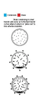
the physical size and capacity of the equipment. Removing it quickly keeps the unit full of steam . As steam condenses, it forms a film of water on the inside of the heat exchanger.

Non-condensable gases do not change into a liquid and flow away by gravity. Instead, they accumulate as a thin film on the surface of the heat exchanger— along with dirt and scale. All are potentialbarriers to heat transfer .

The need to remove air and CO2.
Air is always present during equipment start-up and in the boiler feedwater. Feedwater may also contain dissolved carbonates which release carbon dioxide gas. The steam velocity pushes the
gases to the walls of the heat exchangers where they may block heat transfer. This compounds the condensate drainage problem because these gases must be removed along with the condensate.

Note that heat radiation from the distribution system causes condensate to form and, therefore, requires steam traps at natural low points or ahead of control valves. In the heat exchangers, traps perform the vital function of removing the condensate before it becomes a barrier to heat transfer. Hot condensate is returned through the traps to the boiler for reuse.
Effect of Air on Steam Temperature
When air and other gases enter the steam system, they consume part of the volume that steam would otherwise occupy. The temperature of the air/steam mixture falls below that of pure steam. Figure next . explains the effect of air in steam lines. Table shows the various temperature reductions caused by air at various percentages and pressures


Effect of Air on Heat Transfer
The normal flow of steam toward the heat exchanger surface carries air and other gases with it. Since they do not condense and drain by gravity, these non-condensable gases set up a barrier between the steam and the heat exchanger surface. The excellent insulating properties of air reduce heat transfer. In fact, under certain conditions as little as ^ of 1% by volume of air in steam can reduce heat transfer
efficiency by 50% . When non-condensable gases (primarily air) continue to accumulate and are not
removed, they may gradually fill the heat exchanger with gases and stop the flow of steam altogether. The unit is then“air bound.”
 |
| FIG 9 |
What the Steam Trap Must Do
The job of the steam trap is to get condensate, air and CO2 out of the system as quickly as they accumulate. In addition, for overall efficiency and economy, the trap must also provide:
1. Minimal steam loss. Table shows how costly unattended steam leaks can be.

2. Long life and dependable service.
Rapid wear of parts quickly brings a trap to the point of undependability. An efficient trap saves money by minimizing trap testing, repair, cleaning, downtime and associated losses.
Rapid wear of parts quickly brings a trap to the point of undependability. An efficient trap saves money by minimizing trap testing, repair, cleaning, downtime and associated losses.
3. Corrosion resistance. Working trap parts should be corrosion resistant in order to combat the damaging effects of acidic or oxygen-laden condensate.
4. Air venting. Air can be present in steam at any time and especially on start-up. Air must be vented for efficient heat transfer and to prevent system binding.
5. CO2 venting. Venting CO2 at steam temperature will prevent the formation of carbonic acid. Therefore, the steam trap must function at or near steam temperature since CO2 dissolves in condensate which has cooled below steam temperature.
6. Operation against back pressure.Pressurized return lines can occur both by design and unintentionally. A steam trap should be able to operate against the actual back pressure in its return system.
7. Freedom from dirt problems. Dirt is an ever-present concern since traps are located at low points in the steam system. Condensate picks up dirt and scale in the piping, and solids may carry over
from the boiler. Even particles passing through strainer screens are erosive and therefore, the steam trap must be able to operate in the presence of dirt.
A trap delivering anything less than all these desirable operating/design features will reduce the efficiency of the system and increase costs. When a trap delivers all these features the system can achieve:
1. Fast heat-up of heat transfer equipment
2. Maximum equipment temperature for enhanced steam heat transfer
3. Maximum equipment capacity
4. Maximum fuel economy
5. Reduced labor per unit of output
6. Minimum maintenance and a long trouble-free service life
Sometimes an application may demand a trap without these design features, but in the vast majority of applications the trap which meets all the requirements will deliver the best results.
STEAM TRAP TYPES
The Inverted Bucket Steam Trap
 |
| FIG 10 |
2. Steam also enters trap under bottom of bucket, where it rises and collects at top, imparting buoyancy. Bucket then rises and lifts valve toward its seat until valve is snapped tightly shut. Air and carbon dioxide continually pass through bucket vent and collect at top of trap.
Any steam passing through vent is condensed by radiation from trap.

1. All-Stainless Steel Traps.
Sealed, tamper-proof stainless steel bodies enable these traps to withstand freeze-ups without damage. They may be installed on tracer lines, outdoor drips and other services subject to freezing.
For pressures to 650 psig and temperatures to 800°F.
2. Cast Iron Traps.
Standard inverted bucket traps for general service at pressures to 250 psig and temperatures to 450°F. Offered with side connections, side connections with integral strainers and bottom inlet—top
outlet connections.
3. Forged Steel Traps.
Standard inverted bucket traps for high pressure, high temperature services (including superheated steam) to 2,700 psig at 1,050°F.
4. Cast Stainless Steel Traps.
Standard inverted bucket traps for high capacity, corrosive service. Repairable. For pressures to 700 psig and temperatures to 506°F.
 |
| FIG 11 |
4. As the valve starts to open, the pressure force across the valve is reduced. The bucket then sinks rapidly and fully opens the valve. Accumulated air is discharged first, followed by condensate. The
flow under the bottom of the bucket picks up dirt and sweeps it out of the trap. Discharge continues until more steam floats the bucket, and the cycle repeats.
The Float and Thermostatic Steam Trap


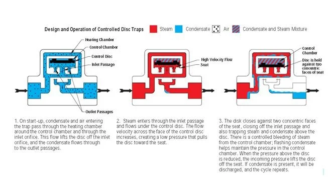
The Controlled Disc Steam Trap

The Thermostatic Steam Trap

1. On start-up, condensate and air arepushed ahead of the steam directly through
the trap. The thermostatic bellows element isfully contracted and the valve remains wide
open until steam approaches the trap.
2. As the temperature inside the trap increases, it quickly heats the charged bellows element, increasing the vapor pressure inside. When pressure inside the element becomes balanced with system pressure in the trap body, the spring effect of the bellows causes the element to expand, closing the valve. When temperature in the trap drops a few degrees below saturated
steam temperature, imbalanced pressure contracts the bellows, opening the valve.
Balanced Pressure Thermostatic Wafer operation is very similar to balanced pressure
bellows described in . The wafer is partially filled with a liquid. As the temperature
inside the trap increases, it heats the chargedwafer, increasing the vapor pressure inside.
When the pressure inside the wafer exceeds the surrounding steam pressure, the wafer
membrane is forced down on the valve seat and the trap is closed. A temperature drop caused by
condensate or non-condensable gases cools and reduces the pressure inside the wafer,
allowing the wafer to uncover the seat.

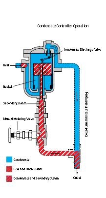
The Automatic Differential Condensate Controller

Trap Selection
To obtain the full benefits from the traps described in the preceding section, it is essential to select traps of the correct size and pressure for a given job and to install and maintain them properly.
. Actual installation and operation of steam trapping equipment should be performed only by experienced personnel. Selection or installation should always be accompanied by competent technical assistance or advice.
Basic Considerations
Unit trapping is the use of a separate steam trap on each steam-condensing unit including, whenever possible, each separate chest or coil of a single machine. The discussion under the Short Circuiting heading explains the “why” of unit trapping versus group trapping. Rely on experience. Select traps with the aid of past experience. Either yours,
Do-it-yourself sizing.
you can easily size steam traps when you know or can calculate:
you can easily size steam traps when you know or can calculate:
1. Condensate loads in lbs/hr
2. The safety factor to use
3. Pressure differential
4. Maximum allowable pressure


thanks for your visit