

Centrifugal clutch case study Centrifugal clutch case study
Centrifugal clutches are to be found on motor-driven equipment such as lawn mowers, mixers and pumps. They engage automatically when the motor speed reaches a pre-determined level, and do not depend on the skill of the operator.

In its simplest form a centrifugal clutch consists of a drive shaft to which are attached two or more spring loaded masses. These are lined with a friction material on their outer surfaces and rotate
inside a drum which is fixed to the output shaft FIG 1
The masses, or ‘bobs’, are free to slide outwards in guides which are rigidly fixed to the input shaft. These are not shown in the above diagram. As the angular velocity of the input shaft increases, the
masses slide outwards and eventually make contact with the drum.
A further increase in speed causes the drive to be transmitted to the output shaft through friction between the masses and the drum.
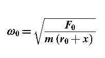
When the masses just make contact with the drum, the tension F₀ in the springs is given by
with the drum, to be found
F₀= m 𝜔₀² (r₀+x)
where
r₀ is the initial radius of rotation from the centre of the shafts to the centre of gravity of the masses
𝜔₀ is the angular velocity at which the masses just make contact with the drum rad /sec
m is mass (kg)
Consider now the normal force and the tangential force between the masses and the drum at some higher speed 𝜔, when the drive is being transmitted to the output shaft.
The normal force between each mass and the drum is equal to the centripetal force, part of which is supplied by the spring tension F₀
R = m 𝜔₀² (r₀+x) - F₀
The tangential friction force between each mass and the drum will be
F = 𝜇 R
F = 𝜇 [m 𝜔² (r₀+x) – F₀]
If the number of masses is n, the torque transmitted will be
KEEP IN MIND The limiting coefficient of friction,𝜇, between two surfaces which can slide
over each other is the ratio of the force required to overcome frictional resistance
and the normal force between the surfaces

Centrifugal clutch case study
Centrifugal clutches are to be found on motor-driven equipment such as lawn mowers, mixers and pumps. They engage automatically when the motor speed reaches a pre-determined level, and do not depend on the skill of the operator.

In its simplest form a centrifugal clutch consists of a drive shaft to which are attached two or more spring loaded masses. These are lined with a friction material on their outer surfaces and rotate
inside a drum which is fixed to the output shaft FIG 1
 |
| FIG 1 |
masses slide outwards and eventually make contact with the drum.
A further increase in speed causes the drive to be transmitted to the output shaft through friction between the masses and the drum.
When the masses just make contact with the drum, the tension F₀ in the springs is given by
spring tension = spring stiffness×extension
F₀=S x
where
x is initial clearance between the masses and the drum
S is spring stiffness
This is also the centripetal force acting on the masses whose radius of rotation is now r₀+x
Equating spring tension and centripetal force enables the angular velocity at which the masses engagewith the drum, to be found
F₀= m 𝜔₀² (r₀+x)

where
r₀ is the initial radius of rotation from the centre of the shafts to the centre of gravity of the masses
𝜔₀ is the angular velocity at which the masses just make contact with the drum rad /sec
m is mass (kg)
Consider now the normal force and the tangential force between the masses and the drum at some higher speed 𝜔, when the drive is being transmitted to the output shaft.
 |
| FIG 2 |
R = m 𝜔₀² (r₀+x) - F₀
The tangential friction force between each mass and the drum will be
F = 𝜇 R
F = 𝜇 [m 𝜔² (r₀+x) – F₀]
If the number of masses is n, the torque transmitted will be
T = n F (D/2)
T =n 𝜇 [m 𝜔² (r₀+x) – F₀] (D/2)
Having calculated the torque transmitted, the power transmitted can be calculated.
power=T𝜔
over each other is the ratio of the force required to overcome frictional resistance
and the normal force between the surfaces


thanks for your visit