

An introduction to Pump types and
applications
The transfer of liquids against gravity existed from time immemorial. A pump is one such device that expends energy to raise, transport, or compress liquids. such as water, brine, oil, etc., to flow across an external resistance. Pumping energy depends on the volume of fluid moved, the resistance against which the pump works, and the machine efficiency. Pumps are used in almost every type of facility and are usually integral to most industrial process applications

Applications
Times have changed, but pumps still operate on the same fundamental principle – expend energy to raise, transport, or compress liquids. Over time, the application of pumps in the agricultural domain has expanded to cover other domains as well. The following are a few main domains that use pumps extensively:
• Water supply: To supply water to inhabited areas.
• Drainage: To control the level of water in a protected area.
• Sewage: To collect and treat sewage.
• Irrigation: To make dry lands agriculturally productive.
• Chemical industry: To transport fluids to and from various sites in the chemical plant.
• Petroleum industry: Used in every phase of petroleum production, transportation, and refinery.
• Pharmaceutical and medical field: To transfer of chemicals in drug manufacture; pump fluids in and out of the body.
• Steel mills: To transport cooling water.
• Construction: Bypass pumping, well-point dewatering, remediation, and general site pumping applications.
• Mining: Heavy-duty construction, wash water, dust control fines and tailings pumping, site dewatering, groundwater control, and water runoff.
Pumps are also used for diverse applications like in transfer of potatoes, to peel the skin of hazelnuts in chocolate manufacture, and to cut metal sheets in areas that are too hazardous to allow cutting by a gas flame torch. The artificial heart is also a mechanical pump. The smallest pump ever made is no bigger than the tip of a finger. It moves between 10 and 30 nl of liquid in one cycle (10- to 30-thousandths of a drop of water). It was not found to have any practical use so maybe it was created just for the records!.
CLASSIFICATION OF PUMPS
Pumps can be classified on various bases Pumps based on their principle of operation are primarily classified into:
• Positive displacement pumps (reciprocating, rotary pumps)
• Roto-dynamic pumps (centrifugal pumps)
• Others.

1- Positive displacement pumps
Positive displacement pumps, which lift a given volume for each cycle of operation, can
be divided into two main classes, reciprocating and rotary
Reciprocating pumps include piston, plunger, and diaphragm types. The rotary pumps
include gear, lobe, screw, vane, regenerative (peripheral), and progressive cavity pumps
1-1 Reciprocating pumps
Reciprocating pumps utilize the principle of a moving piston, plunger, or diaphragm to draw liquid into a cavity through an inlet valve and push it out through a discharge
valve.
They can handle a wide range of liquids, including those with extremely high viscosities, high temperatures, and high slurry concentrations due to the pump’s basic operating principle, i.e., the pump adds energy to the liquid by direct application of force, rather than by acceleration.
piston or Plunger pumps (power pumps)
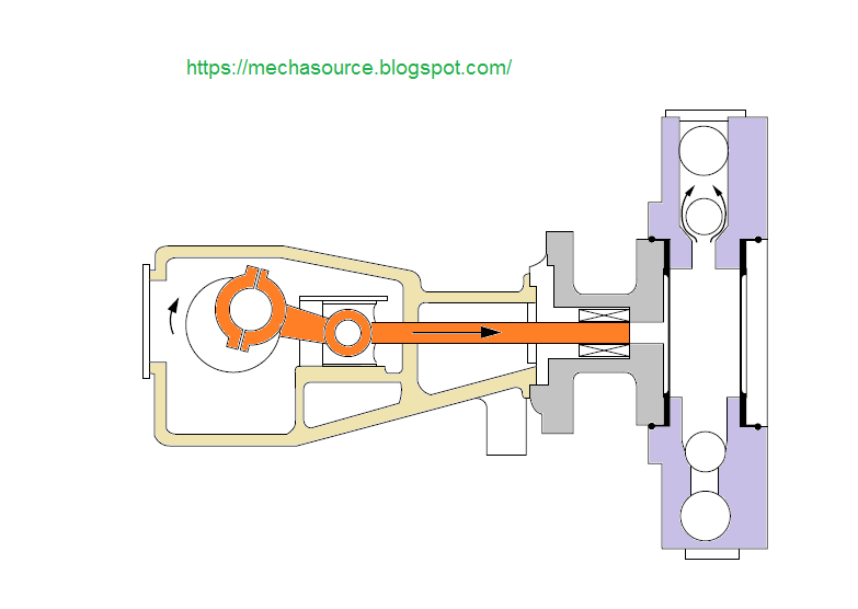
Plunger pumps comprise of a cylinder with a reciprocating plunger in it (Figure 1). The head of the cylinder houses the suction and the discharge valves. In the suction stroke, as the plunger retracts, the suction valve opens causing suction of the liquid within the cylinder.
In the forward stroke, the plunger then pushes the liquid out into the discharge header. these pumps are used normally for high pressure, low flow applications, typically carbonate, amine service or high pressure water or oil services. They can either be horizontal or vertical.
 |
| FIG 1 |
Diaphragm pumps are inherently plunger pumps. The plunger, however, pressurizes the hydraulic oil and this pressurized oil is used to flex the diaphragm and cause the pumping of the process liquid.(FIG 2)
Diaphragm pumps are primarily used when the liquids to be pumped are hazardous or toxic.
the pump being capable of pumping against pressures no greater than that of the motive fluid.
 |
| FIG 2 |
Metering pumps
A diaphragm type metering pump or 'proportioning' pump (FIG 3) . This type of pump is most commonly used for chemical injection service when it is required to precisely control the amount of chemical or inhibitor being injected into a flowing process stream. Volume control is provided by varying the effective stroke length
 |
| FIG 3 |
BLOW CASE PUMP
This is a special configuration of a positive displacement pump (Figure 4). It consists of two pressure chambers that are alternately filled with liquid. When a chamber is filled, air or steam is forced into the chamber. This causes the contents to be discharged into the system. The two chambers alternate in this action, resulting in a fairly constant discharge.
It is popular for pumping hot condensate: because there is no heat loss, and flashing liquid can be transferred.
 |
| FIG 4 |
1-2 Rotary pumps
This pump is a positive displacement pump that consists of the following:
- a chamber that contains gears, cams, screws, lobes, plungers, or similar devices actuated by rotation of the drive shaft;
- no separate inlet and outlet valves;
- tight running clearances
Gear pump
In this pump, fluid is carried between gear teeth and displaced when the teeth engage. The mating surfaces of the gears mesh and provide continuous sealing. Either rotor is capable of driving the other.
Gear pumps are of two types:
1. External gear pump (FIG 5)
2. Internal gear pump. (FIG 6 )
External gear pumps have all gear cut externally. These may
have spur, helical, or herringbone gear teeth and may use
Internal gear pumps have one rotor with internally cut gear
teeth that mesh with an externally cut gear. These pumps
are made with or without a crescent-shaped partition.
Gear pumps are used for small
volume lube oil services and liquids of very high viscosity (asphalt,
polyethylene, etc).
 |
| FIG 5 |
 |
| FIG 6 |
In this pump, liquid is carried between rotor lobe surfaces from the inlet to the outlet. The rotor surfaces mate and provide continuous sealing. The rotors must be timed by separate means. Each rotor has one or more lobes
The operation of the lobe pumps is similar to the operation of the external gear pumps (Figure 7 ). Here, each of the lobes is driven by external timing gears. As a result, the lobes do not make contact.
Lobe pumps are frequently used in food applications because they can handle solids without damaging the product.
 |
| FIG 7 |
This pump utilizes vanes in the form of blades, buckets, rollers, or slippers, which act in conjunction with a cam to draw liquid into and force it from the pump chamber. (figure 8 )
A vane pump may be constructed with vanes in either the rotor or stator and with radial hydraulic forces on the rotor balanced or unbalanced. The vane in rotor pumps may be made with constant or variable displacement pumping elements. Vane pumps are ideally suited for low-viscosity, nonlubricating liquids.
 |
| FIG 8 |
A progressive cavity pump consists of only one basic moving part, which is the driven metal rotor rotating within an elastomer-lined (elastic) stator
with internal threads. The rotor threads are eccentric to the axis of rotation. (figure 9 ) illustrates a single-screw pump commonly called a progressive cavity pump. this pumps are solutions to the special pumping problems of municipal and industrial wastewater and waste processing operations. Industries, such as, chemical, petrochemical, food, paper and pulp, construction, mining, cosmetic, and industrial finishing, find these pumps are ideally suited for pumping fluids with nonabrasive material inclusion.
 |
| FIG 9 |
As shown in Figure 10 , the impeller has a large number of small radial vanes on both of its sides. The impeller runs in a concentric circular casing. Interaction between the casing and the vanes creates a vortex in the spaces between the vanes and the casing, and the mechanical energy is transmitted to the pumped liquid.
Peripheral pumps are relatively inefficient and have poor self-priming capability. They can handle large amounts of entrained gas. They are suitable to low flow and high pressure applications with clean liquids
 |
| FIG 10 |
Screw pump
In this pump, liquid is carried in spaces between screw threads and is displaced axially as these threads mesh. The screw and wheel pump (Figure 11 ) depends upon a plate wheel to seal the screw so that there is no continuous cavity between the inlet and outlet. Multiple screw pumps have multiple external screw threads. Such pumps may be timed or untimed. illustrates a timed screw pump
The screw pumps are ideally suited for a variety of marine and offshore applications such as fuel-injection, oil burners, boosting, hydraulics, fuel, lubrication, circulating, feed, and many more. The pumps deliver pulsation free flow and operate with low noise levels. These pumps are self-priming with good efficiency. These pumps are also ideal for highly viscous liquids.
 |
| FIG 11 |
In this pump, liquid is drawn in and forced out by pistons that reciprocate within cylinders.The valving is accomplished by rotation of the pistons and cylinders relative to the ports. The cylinders may be axially or radially positioned and arranged for either constant or variable displacement pumping.
 |
| FIG 12 |
In this pump figure 13, the liquid pumping and sealing action depends on the elasticity of the flexible members. The flexible member may be a tube, a vane, or a liner.
 |
| FIG 13 |
Circumferential Piston Pump
In this pump (Figure 14), liquid is carried from inlet to outlet in spaces between piston surfaces. There are no sealing contacts between rotor surfaces.
• In the external circumferential piston pump, the rotors must be timed by separate means and each rotor may have one or more piston elements.
• In the internal circumferential piston pump, timing is not required, and each rotor must have two or more piston elements.
 |
| FIG 14 |
Roto-dynamic pumps raise the pressure of the liquid by first imparting velocity energy to it and then converting this to pressure energy. These are also called centrifugal pumps.
Centrifugal pumps include radial, axial, and mixed flow units.
A radial flow pump is commonly referred to as a straight centrifugal pump; the most common type is the volute pump. Fluid enters the pump through the eye of impeller, which rotates at high speed. The fluid is accelerated radially outward from the pump casing. A partial vacuum is created that continuously draws more fluid into the pump if properly primed.
In the axial flow centrifugal pumps, the rotor is a propeller. Fluid flows parallel to the
axis of the shaft. The mixed flow, the direction of liquid from the impeller acts as an
in-between that of the radial and axial flow pumps.
COMPONENTS OF A ROTARY PUMP
• The rotary pump consists of the following parts:
- pumping chamber
- body
- endplates
- rotating assembly
- seals
- bearings
- timing gears
- relief valves
2-1 CENTRIFUGAL PUMPS
The centrifugal pumps are by far the most commonly used of the pump types. Among all the installed pumps in a typical petroleum plant, almost 80–90% are centrifugal pumps.
Centrifugal pumps are widely used because of their design simplicity, high efficiency, wide range of capacity, head, smooth flow rate, and ease of operation and maintenance
All centrifugal pumps use but one pumping principle in that the impeller rotates the liquid at high velocity, thereby building up a velocity head (Figure 15).
At the periphery of the pump impeller, the liquid is directed into a volute. The volute commonly has an increasing crosssectional area along its length so that as the liquid travels along the chamber, its velocity is reduced.
 |
| FIG 15 |
Radial Flow
A pump in which the head is developed principally by the action of centrifugal force. The liquid enters the impeller at the hub and flows radially to the periphery (Figure 16).
 |
| FIG 16 |
Mixed Flow
A pump in which the head is developed partly by centrifugal force and partly by the lift of the vanes on the liquid.
This type of pump has a single inlet impeller with the flow entering axially and discharging in an axial/radial direction (Figure 17 ).
 |
| FIG 17 |
Axial Flow
This pump, sometimes called a propeller pump, develops most of its head by the propelling or lifting action of the vanes on the liquid. It has a single inlet impeller with the flow entering axially and discharging nearly axially (Figure 18 ).
 |
| FIG 18 |
Turbine pumps obtain their name from the many vanes machined into the periphery of the rotating impeller. Heads over 900 feet are readily developed in a two-stage pump.
The impeller, which has very tight axial clearance and uses pump channel rings, displays minimal recirculation losses. The channel rings provide a circular channel around the blades of the impeller from the inlet to the outlet.(figure 19)
Liquid entering the channel from the inlet is picked up immediately by the vanes on both sides of the impeller and pumped through the channel by the shearing action. The process is repeated over and over with each pass imparting more energy until the liquid is discharged
 |
| FIG 19 |
Pumps are used to build the pressure in a liquid and if necessary to contain it within the casing. At the interface of the rotating shaft and the pump casing, mechanical seals are installed to do the job of product containment. However, seals are prone to leakages and this maybe unacceptable in certain critical applications. To address this issue, sealless pumps have been designed and manufactured.
These are of two types – canned and magnetic drive pumps:
1. Canned pumps: In the construction of this second type of sealless pump, the rotor comprises of an impeller, shaft, and the rotor of the motor. These are housed within the pump casing and a containment shell (Figure 20).
The hazardous or the toxic liquid is confined within this shell and casing. The rotating flux generated by the stator passes through the containment shell and drives the rotor and the impeller.
 |
| FIG 20 |
The driven magnets take their drive from the rotating drive magnets, which are assembled on a different shaft that is coupled to the prime mover.
 |
| FIG 21 |
Viscous Drag or Disk Pump
The viscous drag pump operation utilizes two principles of fluid mechanics(figure 22): boundary layer and viscous drag. These phenomena occur simultaneously whenever a surface is moved through a liquid.
Advantages of using a viscous drag pump
- minimal wear with abrasive materials
- gentle handling of delicate liquids
- ability to easily handle highly viscous liquids
- freedom from vapor lock
 |
| FIG 22 |
Screw Centrifugal Pump
This pump incorporates a large-diameter screw instead of the more common radial impeller that is found in centrifugal pumps (Figure 23).
Because the pumped material enters at a low entrance angle, a low shear, low turbulence condition exists, which results in very gentle handling of the liquid. The gentle handling makes it possible to pump slurries of fruits and vegetables without undue breakup of constituents
 |
| FIG 23 |
The basic concept of this pump is unique (Figure 24). Liquid enters the intake manifold and passes into a rotating case where centrifugal force accelerates it. A stationary pickup tube situated on the inner edge of the case, where pressure and velocity are the greatest, converts the centrifugal energy into a steady pulsation-free high pressure stream.
The following characteristics attest to the simplicity of the pump:
- only one rotating part (the casing)
- the seal is exposed only to suction pressure
- no seal is required at the high pressure discharge
 |
| FIG 24 |
A vortex pump comprises a standard concentric casing with an axial suction intake and a tangential discharge nozzle (Figure 25). The straight radial-bladed impeller is axially recessed in the casing.
The rotating impeller creates a vortex field in the casing that motivates the liquid from the centrally located suction to the tangentially located discharge. Because the pumped liquid does not have to flow through any vane passages, solid content size is limited only by the suction and discharge diameters. this pump can handle high solid-content liquids, entrained gas liquids, and stringy sewage while requiring a relatively low NPSH.
 |
| FIG 25 |
• Centrifugal pumps comprise of the following parts:
- casing
- impeller
- wearing rings (impeller, casing)
- shaft and shaft sleeves
- stuffing box
- mechanical seals
- bearings
- bearing frame


thanks for your visit