


Rupture Discs introduction and study
Chemical plants, tanks, reactors, silos and any other equipment working under pressure may be damaged or destroyed by non controlled pressure rises.
Protection of personnel and equipment from this risk is achieved with safety devices that provide an adequate fluid outlet, venting the excess pressure.
 |
| figure 1 |
principle work and application
The rupture disc is designed to burst open at a predetermined pressure. A rupture disc cannot be reseated and, therefore, must be replaced once it has performed its relieving function. Rupture discs have the advantage of being leak tight up to the rupture pressure and of being capable of relieving large rates of flow. The set pressure of rupture discs cannot be adjusted.
Pressure relief valves and rupture discs may be used in series. In such cases, rupture discs are designed to rupture at a pressure approximately 5 to 10% above the pressure at which a relief valve is designed to activate. In this manner, the rupture disc acts as a backup device. It can be used upstream of a safety relief device to protect the valve components from corrosion or malfunction due to process materials. Rupture discs are occasionally placed downstream of relief valves in manifolded relief
discharge systems where it is necessary to protect the discharge side of the pressure relief valve from corrosion
 |
| figure 2 |
The rupture disc (or bursting disc) is a very versatile device and is extremely useful at very low and very high running pressure, in contact with toxic or expensive fluids when leaks are not allowable. It is a very reliable device without maintenance problems not with standing its low cost.
 |
| figure 3 |
Rupture of the membrane takes place when tensile forces exceed the ultimate tensile stress of the membrane material figure 4.The relevant material property that determines failure is the Young's modulus. Correct installation is essential. If installed upside down, the reliability of the overpressure safety device is compromised.
 |
| figure 4 |
types
Rupture discs belong to 3 families:
Metal
o Conventional or forward acting Tension loaded figure 5
o Compression or reverse acting Compression loaded figure 6
Graphite. Shear loaded figure 7
selection
Disc selection depends from exercise conditions of the equipment to be protected: Conventional discs have a flat or concave surface exposed to the pressure. Bursting happens when the pressure (or depression) overcomes the mechanical resistance of the material, after having gradually increased the camper of the disc. Reverse acting discs have a convex surface exposed to the pressure. The shape of the disc does not change until the pressure reaches the bursting point. Graphite discs are recommended at low exercise pressure in contact with aggressive fluids. They are normally used at low and medium pressure.
Minimum and maximum bursting pressures are dependent from: Disc model Dimension Material
Minimum and maximum working temperatures are dependent from disc material as in following table

Working temperature of discs with a lining is also dependent from lining material
 assembly
WARNING: Before attempting to assemble the rupture disc and rupture disc holder, confirm that the seat area of the rupture disc is designed to fit the rupture disc holder.
1. Place holddown on a work surface with rupture disc seating surface up. (See fig. 8)
2. Install optional O-Ring, if applicable, in holddown.
3. Place rupture disc into holddown with flow arrow on tag pointing in the same direction as holddown flow arow.
4. Install optional O-Ring in base if applicable.
5. Carefully align and place base onto rupture disc with flow arrow in the same direction as disc and
holddown flow arrows.
6. Rotate base to align sideclip holes
7. Install sideclips and tighten.
8. lubricate capscrews with a light oil if required. Lubricate both the threads and the underside of the head. Turn assembly over, install lubricated capscrews and tighten until recessed and snug in
the holder.
9. Check gap between base and holddown. The gap must be the same size on all sides of the assembly. This can be assured by measuring the distance between the holddown and base at various places around the circumference of the assembly. Adjust preassembly screws if necessary to provide an even gap. (See fig. 9)
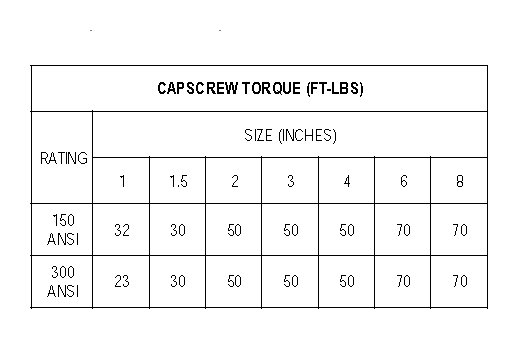
10. torque capscrews to values shown in Tables until the full torque is achieved on all capscrews.
INSTALLATION
1. Place gaskets on top and bottom of assembly.
2. Carefully slide rupture disc assembly between companion flanges.
WARNING: Double check the orientation of the rupture disc. Verify flow arrows on the holder and disc tag are pointed in the same direction as process flow.
3. If necessary, clean threads on studs and nuts. Wire brushing is usually sufficient.
4. Finger tighten flange bolt nuts.
5. Refer to Tables to obtain torque value. Locate nominal disc size and flange rating. This is the required torque value.

6. Using the crisscross pattern to apply torque
7. After recommended torque has been achieved, perform a final tightening in a clockwise bolt-to-bolt fashion to ensure that all studs have equal loading.
CHECK GAP BETWEEN BASE AND HOLDDOWN AFTER EACH TORQUE STEP. MAINTAIN AN EQUAL DISTANCE BETWEEN COMPANION FLANGE FACES ON ALL SIDES.
8. Experience has shown that, in some installation conditions, it may be necessary to re-torque the flange bolting after the system has operated through normal pressure and temperature cycles. Under normal operation conditions,
the rupture disc should be replaced yearly. Severe operating conditions may require that the rupture disc be replaced more often.
sizing
Use of this equation complies with ASME B31 requirements, but its use should be reviewed with respect to local pressure vessel codes

where:
A = required rupture disc area, mm² (in²)
n = conversion coefficient, 2.280 x 10⁴ for SI units and 0.0263 for IP units.
Q = flow, m³/s (gpm)
K = flow coefficient (K = 0.62 per ASME B31)
s.g. = specific gravity
P = relieving pressure, MPa (psi)
Metal
o Conventional or forward acting Tension loaded figure 5
o Compression or reverse acting Compression loaded figure 6
Graphite. Shear loaded figure 7
 |
| figure 5 |
 |
| figure 6 |
 |
| figure 7 |
selection
Disc selection depends from exercise conditions of the equipment to be protected: Conventional discs have a flat or concave surface exposed to the pressure. Bursting happens when the pressure (or depression) overcomes the mechanical resistance of the material, after having gradually increased the camper of the disc. Reverse acting discs have a convex surface exposed to the pressure. The shape of the disc does not change until the pressure reaches the bursting point. Graphite discs are recommended at low exercise pressure in contact with aggressive fluids. They are normally used at low and medium pressure.
Minimum and maximum bursting pressures are dependent from: Disc model Dimension Material
Minimum and maximum working temperatures are dependent from disc material as in following table

Working temperature of discs with a lining is also dependent from lining material

WARNING: Before attempting to assemble the rupture disc and rupture disc holder, confirm that the seat area of the rupture disc is designed to fit the rupture disc holder.
 |
| figure 8 |
1. Place holddown on a work surface with rupture disc seating surface up. (See fig. 8)
2. Install optional O-Ring, if applicable, in holddown.
3. Place rupture disc into holddown with flow arrow on tag pointing in the same direction as holddown flow arow.
4. Install optional O-Ring in base if applicable.
5. Carefully align and place base onto rupture disc with flow arrow in the same direction as disc and
holddown flow arrows.
6. Rotate base to align sideclip holes
7. Install sideclips and tighten.
8. lubricate capscrews with a light oil if required. Lubricate both the threads and the underside of the head. Turn assembly over, install lubricated capscrews and tighten until recessed and snug in
the holder.
9. Check gap between base and holddown. The gap must be the same size on all sides of the assembly. This can be assured by measuring the distance between the holddown and base at various places around the circumference of the assembly. Adjust preassembly screws if necessary to provide an even gap. (See fig. 9)
 |
| figure 9 |
10. torque capscrews to values shown in Tables until the full torque is achieved on all capscrews.
INSTALLATION
 |
| figure 10 |
1. Place gaskets on top and bottom of assembly.
2. Carefully slide rupture disc assembly between companion flanges.
WARNING: Double check the orientation of the rupture disc. Verify flow arrows on the holder and disc tag are pointed in the same direction as process flow.
3. If necessary, clean threads on studs and nuts. Wire brushing is usually sufficient.
4. Finger tighten flange bolt nuts.
5. Refer to Tables to obtain torque value. Locate nominal disc size and flange rating. This is the required torque value.


6. Using the crisscross pattern to apply torque
7. After recommended torque has been achieved, perform a final tightening in a clockwise bolt-to-bolt fashion to ensure that all studs have equal loading.
CHECK GAP BETWEEN BASE AND HOLDDOWN AFTER EACH TORQUE STEP. MAINTAIN AN EQUAL DISTANCE BETWEEN COMPANION FLANGE FACES ON ALL SIDES.
8. Experience has shown that, in some installation conditions, it may be necessary to re-torque the flange bolting after the system has operated through normal pressure and temperature cycles. Under normal operation conditions,
the rupture disc should be replaced yearly. Severe operating conditions may require that the rupture disc be replaced more often.
sizing
Use of this equation complies with ASME B31 requirements, but its use should be reviewed with respect to local pressure vessel codes

where:
A = required rupture disc area, mm² (in²)
n = conversion coefficient, 2.280 x 10⁴ for SI units and 0.0263 for IP units.
Q = flow, m³/s (gpm)
K = flow coefficient (K = 0.62 per ASME B31)
s.g. = specific gravity
P = relieving pressure, MPa (psi)


This article are supper help full if you want to know more about disc model then please click here.
ReplyDelete