

An Introduction To (Journal) Sleeve Bearing Failure Modes and Their Causes
Bearings for rotating shafts can be divided into two main classes: ball/roller/needle and sleeve bearings.
Sleeve bearings can be further classified by the type of material used. They have been listed in order of increasing initial cost:
(a) Bronze bearings
(b) White-metal bearings (babbit)
(c) Sintered metal bearings
(d) Aluminum
(e) Plastics
These three (a.b.c ) types cover more than 90 per cent of sleeve bearings. . The selection of the type of bearing depends on many factors like accessibility and availability for periodical inspection and maintenance; speed and type of load on the shaft; environment; cost, etc. Certain failure modes and failure mechanisms are common to all the three types of bearings

Common Failure Modes
The most common failure mode is overheating. If the bearing is allowed to run despite overheating, the bearing metal may melt, the shaft may get scored, or the shaft may even break. Overheating is the first sign that a bearing failure is imminent see figure 1.
The normal temperature of the sleeve bearing may be only a few tens of degrees Celsius over the ambient temperature. The normal temperature rise will vary from machine to machine and from design to design. The temperature rise limits for any particular design and application may be ascertained from the manufacturer. It would be ideal if temperatures are measured carefully on 10 to 20 machines. The average temperature rise and the standard deviation should be calculated . The average plus three times the standard deviation should be taken as the upper temperature rise limit for the case in question.
 |
| FIG 1 |
While measuring temperatures for the purpose of determining the limits, it should be ensured that the temperature measured is always at the same spot, using an identical method of measurement, when the shaft speed and load are at their highest level and allowing enough time for stabilisation of the temperature. For condition monitoring during service, similar procedures should be adopted
In the case of medium and high speed bearings, the lubricating oil is pulled into the space between the shaft and the bearing and a very thin but significant film of oil separates the shaft and the sleeve bearing figure 2. This film helps to minimise the friction, the energy loss and the temperature rise of the bearing.
 |
| FIG 2 |
Failure of this film of oil is the starting point of sleeve bearing failures. There is metal to metal contact, excessive friction, excessive heat and eventual failure of the bearing. All possible causes and circumstances that could lead to failure of the oil film should be investigated. The most common causes generally in order of probability of occurrence are as follows:
(a) Lack of lubricant, though very obvious, is also one of the most common causes of bearing failures. The lack of lubricant could be due to a number of causes:
(i) Lack of constant or timely replenishment of the lubricant.
(ii) Leakage of the lubricant due to either a defect in a rubber seal, a fracture or blow hole in the casing of the bearing.
(b) Contamination of the lubricant causing it to thicken; or become very thin; or contain abrasive foreign matter in it.
(c) Excessive or abnormal loading on the bearing.
(d) Excessive or inadequate clearances between shaft and bearing due to initial installation error, or excessive clearance due to wear of the bearing sleeve.
(e) Poor surface finish of the bearing surface and/or the shaft surface.
(f) Heat input into the bearing from an adjacent source of heat, that had not been considered in the original design.
 |
| FIG 3 |
1- Failures due to Lubricants
Oil-Film Instability
The primary vibration frequency components associated with fluid-film bearings problems are in fact displays of turbulent or nonuniform oil film. Such instability problems are classified as either oil whirl or oil whip depending on the severity of the instability.
Machine-trains that use sleeve bearings are designed based on the assumption that rotating elements and shafts operate in a balanced and, therefore, centered position. Under this assumption, the machine-train shaft will operate with an even, concentric oil film between the shaft and sleeve bearing. For a normal machine, this assumption is valid after the rotating element has achieved equilibrium. When the forces associated with rotation are in balance, the rotating element will center the shaft within the bearing.
However, several problems directly affect this self-centering operation. First, the machine-train must be at designed operating speed and load to achieve equilibrium. Second, any imbalance or abnormal operation limits the machine-train’s ability to center itself within the bearing.
 |
| FIG 4 |
Change in Dynamic Viscosity of the Lubricating
Dynamic viscosity at operating temperature is the only property representing the lubricant in the HD oil film thickness calculation. In general, reduction in dynamic viscosity will reduce the oil film thickness. Under severe transient conditions reduction of the oil film thickness may change the HD
lubrication condition to a mixed lubrication regime and increase the risk of bearing surface contact and wear. If not corrected, it will cause bearing failure. In opposite conditions when the dynamic viscosity is too high, an increase in drag and friction will result in local heat generation, which may increase the rate of chemical reaction within the oil film. In conditionbased maintenance programs, kinematic viscosity at 40 °C (or occasionally at 100 °C) is used to measure this property. The
assumption is that in most industrial applications, lubricant density is not significantly changed in the measured temperature of interest (for example, 40 °C or 100 °C) and trending kinematic viscosity can provide adequate prediction of the lubricant’s ability to form a reliable and sustainable HD oil
film. Newer methods exist or are being developed that will measure dynamic viscosity directly. These methods may in time become commonly used in this application.
Deterioration of Lubricating Oil Chemistry—The HD
lubrication will also depend on the complex relationship between properties of oil-to-metal adhesion and oil-to-oil cohesion. Applying a constant shear stress on the lubricating oil film may lead to physical damage to the lubricant molecules.
The presence of atmospheric oxygen may initiate chemical reactions such as oxidation. High temperature and pressure will accelerate these reactions and lubricant molecules thermal breakdown. Finally, lubricating oil will also deteriorate by the additive depletion process (for example, due to expected performance). The depletion rate would depend on the additive type, applications, and operating conditions. The consequences of these chemical changes will influence several critical
properties such as cohesion, adhesion, surface tension, etc.
Some visible changes will include an increase in foaming characteristics, air release, sludge and varnish formation, or reduce oil solubility characteristics.
Increase in Gaseous, Liquid, and Solid Particle Contamination
An excessive amount of undissolved gas bubbles in the oil weakens the load carrying capacity of the lubricating film. If the gas is reactive, it can promote chemical degradation of the lubricant which may change the physical characteristics of the oil.
A large amount of liquid contaminants, particularly those having significantly different viscosity or density, may influence the dynamic viscosity. If this liquid has chemical reactivity with the lubricant, it could affect its performance characteristics. An example is free water which may not support the external load acting on the bearing. It could also hydrolyze some of the additives, affecting their performance
The presence of a moderate concentration of small solid particle contamination is of less concern in HD lubrication, assuming the particle sizes are smaller than the oil film thickness. However, the presence of solid particles is more harmful in boundary and mixed lubrication conditions. The
presence of solid particles may increase the risk of some particles being imbedded in soft bearing surfaces and generate abrasive wear to the mating hard surfaces. In applications with a hydrostatic lift system, large solid particles may scratch surfaces around oil grooves, reducing bearing capability to generate the required hydrostatic lift during start up or shut
down operations.
 |
| FIG 5 |
Changes in the relative speed of bearing surfaces or to the wedge profile will also influence the HD oil film. During start up or shut down operations, plain bearings most likely will operate for a short period under mixed or even boundary lubrication. At these conditions there is an increased risk of bearing surface contact resulting in surface wear, which may temper the profile of the lubricating oil wedge, thus affecting the oil film formation.
2- Bearing Surface Damage Due to Scoring and Wire Wool
The term scoring is used to describe parallel or circumferential grooves on the bearing surface caused by dirt or debris presence between the bearing and mating surfaces. These particles can originate from wear of journal, bearing surfaces, system components, or from the surrounding environment.
Small particles may also cause polishing of bearing surface that will have little effect on the bearing performance, providing the roughness and particle size do not exceed the thickness of the HD oil film. Large particles usually generate deep scores on the soft bearing surface or become embedded in the soft material generating scores on hard journal surface. Severe cases of damage to the mating surface can occur when shaft material contains chromium or manganese. Large embedded particles
(approximately 1 mm) containing chromium or manganese in excess of 1 % may form a hard deposit of material by reaction with the steel journal. This mechanism is self-propagating when started and is usually referred to as “wire wool” damage.
 |
| FIG 6 |
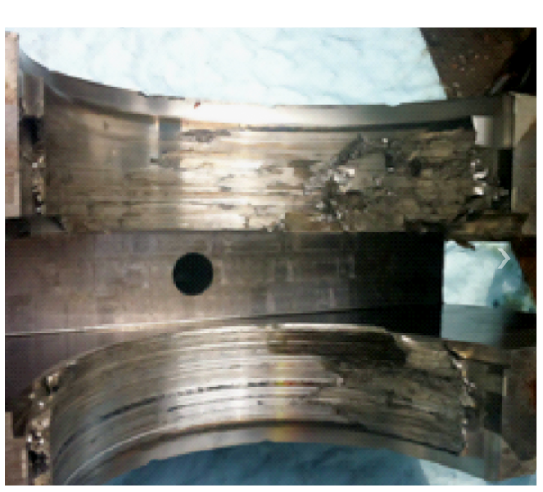
3- Bearing Surface Damage Due to Wiping
Bearing materials are normally chosen for their ability to conform to the mating surface. Therefore a slight wipe near one edge of the bearing indicates that the bearing surface layers melt and wipe
in order to accept a particular configuration. Severe wipes lead to a new film thickness profile. Some associated problems with tighter clearances may occur during rapid start up of a cold machine, where the heat generated within the oil film may cause the shaft temperature to rise more rapidly than the
bearing housing. Differential expansion of the shaft can cause a temporary reduction in bearing clearance, which in severe cases may cause metal-to-metal contact in the zone of minimum clearance.
 |
| FIG 7 |
Cracking occurs when dynamic loads exceed temperature dependent white metal bearing alloy strength and is generally attributed to fatigue. A characteristic of fatigue damage is that the cracks
may reach areas near the bond but they will then propagate through the white metal bearing alloy, leaving a portion of this alloy still adhering to the backing. The remaining white metal bearing alloy is often polished by the loose particles over a period of time. The fatigue strength of white metal bearing alloys decreases with increased temperature. Partial loss of oil supply may result in overheating and produce fatigue damage. Intergranular cracking is another form of fatigue mechanism and may be caused by a short period of overheating. The high temperature zone extends deeper than the surface layer of a single wipe so that more of the white metal bearing alloy is
weakened. Frictional forces on the surface from contact with the shaft may cause partial shearing of the white metal bearing alloy opening up the cracks. This type of damage often extends only about half way through the thickness of the lining, presumably because the lower layer has more strength, being cooled from the backing. In general, surface cracking causes high vibration.
The “specific loading” of a bearing is a critical parameter for determining the load carrying capabilities of a bearing. The specific loading of a bearing is the ratio of the applied force to the cross-sectional area of the bearing. In a simple case, the applied force is equal to the rotor weight that is supported by the bearing. The cross-sectional area of a bearing is the axial length of the bearing surface multiplied by the diameter of the bearing bore.

 |
| FIG 8 |
High velocity regions, particularly at bearing edges or around sudden changes in bearing steps, may cause bearing material removal parallel to lubricating oil flow. This will form “canyons” which
may change lubricant flow pattern, reducing the local film thickness and oil load carrying capacity. This wear may be amplified by the presence of solid particles in the oil. Another cause of erosion in journal bearings is cavitation where the fluid pressure increases in the load zone of the bearing. No metal-to-metal contact is needed. In the cavitation process vapor bubbles in the fluid are formed in low-pressure regions and are collapsed (imploded) in the higher-pressure regions of the oil system. The implosion can be powerful enough to create holes or pits, even in hardened metal when the implosion occurs at the metal surface.
 |
| FIG 9 |
6- Bearing Surface Damage Due to Pitting
In most cases, pits have a hemispherical form, uniformly distributed over the zone area and may also be found on the mating surface. One cause of pitting is the discharge of an electric current through the oil film, resulting in spark erosion. In such cases, the pits are clean and shiny. If the pits have a black deposit, the pitting is attributed to a different mechanism.
 |
| FIG 10 |
7- Bearing Damage Initiated by Fretting on a Pivot
The reddish-oxide is formed by fretting around the concentrated contact area at the pivot of pad bearings. It may be caused by pad overload or external vibration from adjacent machinery. Fretting damage may also occur during standby operation.
 |
| FIG 11 |
Corrosive wear is caused by increased oil acidity due to formation of oxidation or hydrolysis products, decomposition of some oil additives or the presence of some contaminants such as water or coolant. This wear mechanism leaches certain elements from the soft bearing materials, leaving the upper bearing surface layer porous and weak. Incompatibility between bearing material and lubricant may also promote the corrosion process. The consequence of this wear is a reduction in the bearing’s load carrying capacity. Corrosion can also cause pitting, although this is not common for tin based white metal bearing alloys. Black tin oxide can be produced by excessive water contamination. These pits are characteristically uneven. Usually this type of corrosion is accompanied by rusting of exposed steel surfaces.
 |
| FIG 12 |
Heat generated from the oil shearing process may cause a local reduction in oil viscosity and film thickness, which can further raise oil temperature. In turn, this may oxidize some oil molecules, forming varnish on the bearing surfaces. Since white metal bearing alloy strength depend on
temperature, this can lead to material softening and flowing of the upper layer. Although wiping does not necessarily occur under such conditions, surface deformation, cracking and discoloration are typical effects of overheating. The consequences of overheating are the reduction of load carrying
capacity and loss of film thickness due to the presence of the varnish layer
 |
| FIG 13 |
10- Bearing Surface Damage Due to Anisotropy
Due to uneven thermal expansion of the tin white metal bearing alloys, severe thermal cycling may lead to cracking along the grain boundaries. This will result in a polishing pattern of white metal bearing alloy surfaces and in extreme cases can cause surface cracking.
 |
| FIG 14 |
11- Bearing Surface Damage Due to Hydrogen
Blistering
Diffused hydrogen from the steel backing shell stops at the white metal bearing alloy bond line because it cannot diffuse through this alloy. As a result, the hydrogen atoms will build up, causing local pressure and breaking the metallurgical bond. The consequence of this process is loss of
clearance at the blister leading to local overheating and damage.
 |
| FIG 15 |
This damage affects copper, copper alloy pads, or shell material. At environmental temperature above 90 °C, tin continues to diffuse to the bond line, forming a thicker layer of copper-tin alloys, leading to a hard, brittle bond line. Over time, white metal bearing alloy lining can completely separate from its backing under minimal impact load. The separation of white metal bearing alloys during operation could lead to loss of clearance, overheating and in extreme conditions to catastrophic bearing failure.
 |
| FIG 16 |
13- Bearing Surface Damage Due to Delamination
The microstructure of tin-based white metal bearing alloy consists of a soft solid solution matrix and intermetallic compounds that are harder than the matrix. One of the degradation mechanisms
involves rapid cooling which suppresses formation and growth of the intermetallic compound cuboids and increases hardness.
14- Bearing Surface Damage Due to Insufficient Clearance
There must be sufficient clearance between the journal and bearing in order to allow an oil film to form. An average diametral clearance of 0.001 inches per inch of shaft diameter is often used. This value may be adjusted depending on the type of bearing material, the load, speed, and the accuracy of the shaft position desired.
 |
| FIG 17 |
15- Bearing Surface Damage Due to Misalignment
Misalignment of the bearing surface to the shaft will cause edge loading on the bearing. Edge load will result in much higher local temperatures, local pressures and much thinner oil film thicknesses. Naturally when any of these factors goes beyond an acceptable limit damage will occur normally as a breakdown in the local oil film and metal to metal contact. It is most clearly seen as uneven contact on the bearing surface as shown.
 |
| FIG 18 |

Do's and Don'ts for Preventing Sleeve Bearing Failures
- Select the type of bearing, the lubricant and the maintenance schedules for its application in accordance with the recommendations of the manufacturer, as applied to the working conditions such as speed, axial and radial loads, temperature, etc.
- Carry out service trials to confirm the selection made as above. During these service trials, monitor the condition of the lubricant and the active surfaces. In the event of appearance of any sign of impending failure investigate fully and make modifications until satisfactory performance is achieved.
- Ensure correct filling of lubricant after every overhaul. Pay particular attention during overhaul to clearances, cylindricity and surface finishes of the active surfaces.
- Ensure correct lubrication at all times in regard to quality and quantity of the lubricant.
- Monitor active surfaces during overhauls. If irregularities are noticed repair shaft surfaces. If cracks, flaking, roughness etc. are seen in the bearing linings repair or replace
the bearing linings.
- Investigate every case of bearing failure in service to determine the root causes and then to eliminate them
-Some of the common causes of failures are:
Absence of lubricant.
Wrong lubricant.
Defective lubricant.
Inadequate lubricant.
Contaminated lubricant.
Axial and angular position error.
Damage during assembly.
Excessive or inadequate clearances.
Excessive wear on active faces.
Poor bonding between lining and shell.
Poor surface finish on active faces.
External heating of bearing.


We are pleased to introduce ourselves as one of the leading suppliers of Bearings since 1990. Named Lakshmi Trading Company. We deal with a various range of products, such as SKF, FAG, ZKL & JAPAN and also Supplier of Plummer Blocks And Sleeves of Various Brands. We are Specialists in Needle Rollers in Delhi, Unit & Rail Guide Bearing in Delhi, Ball Screw With Net Various make like INA, IKO, HAWIN, ABBA, Etc.
ReplyDeletePlain Bearing in Delhi
Jewel Bearing in Delhi
Fluid Bearing in Delhi
Flexure Bearing in Delhi
thanks for sharing this blog. Unotech Engineering offers a complete bouquet of components for on-road & off-road applications. Engine components, Suspension parts & Power train, Locomotive & Defense components.
ReplyDeleteengine bearings