

An Introduction To Pressure Regulators ,Types ,Selection And Application
Introduction
The primary function of a regulator is to reduce high-pressure gas in a cylinder or process line to a lower, usable level as it passes from the cylinder to a piece of equipment. A regulator is not a flow control device. It is used to control delivery pressure only.
 Pressure regulators are valves that automatically cut off the flow of a gas or liquid when it is at a certain pressure. Regulators are also used to allow high-pressure fluid supply tanks or lines to be reduced to a usable and safe pressure for different applications. Pressure regulators are found in many common home and industrial applications, including heating furnaces, gas grills and even medical and dental equipment.
Three Basic Elements
The Three Basic Elements are:
1. The LOADING MECHANISM provides the means by which the operator can set the force that determines the outlet (control) pressure of the regulator. is a term commonly used for outlet pressure.
1-2- Backpressure Regulator Valve (BPR)
The function of a backpressure regulator is to limit and precisely control the upstream pressure of a gas or liquid (from a tank, pump, etc) and is much more accurate than a relief valve. Most direct spring operated safety relief valves have a high reseating pressure which is inconsistent and unreliable. This is the primary difference between a safety relief valve and a backpressure regulator. A safety relief valve is designed to protect downstream personnel and equipment should over-pressurization take place. As such, when it's set pressure is overcome, it will blow wide open immediately and exhaust all of the pressure. It needs to be able to handle the full flow of the system in order to rapidly exhaust to protect downstream apparatus. A backpressure regulator is not a safety device, it is designed for precision upstream pressure control. When the regulator set-point is overcome, it will "crack" open (not blow wide open) and try to exhaust just the excess pressure above the set-point. When it cracks open, it uses its sensing element (relief valve's do not have sensing elements) to reseat very close to its original set pressure.
The load element provides the force which is in turn transmitted through the SENSING element and to the CONTROL element, to provide the desired outlet pressure. It provides a preload force which establishes the demand level of the regulated or outlet pressure.
There are four types of loading:
• Spring Load
• Dome Load (also called gas or liquid loading)
• Air Load
• Combination of Spring and Dome Load
The spring load is determined by the amount of compression placed on the spring by the operator. This is accomplished by turning the regulator knob or adjusting screw in a clockwise
direction (Figure 9). The knob is turned, compressing the load spring, until the desired outlet
or set pressure is reached on the regulator's outlet pressure gauge.
2-2- Dome-Loaded Regulators
The second loading method is called dome load (Figure 10 ). Instead of a spring, pressure in the dome area is used to provide loading force to the regulator. This is accomplished by sealing the dome area to prevent leaks and then pressurizing it with gas or liquid coming from a pilot regulator.
The pressure in the dome determines the regulator's outlet pressure. The dome pressure is essentially equal to the regulator outlet pressure.
In Figure 10 , a dome loaded regulator is connected to a venting regulator. The venting regulator acts as a pilot regulator and provides the loading pressure to the dome of the dome loaded regulator. To set the pressure in the dome, the pressure coming from the pilot regulator is adjusted until the outlet pressure gauge of the dome regulator reads the desired set pressure.
The slight difference is primarily due to the control element (valve) spring force which counteracts the dome load pressure force.
When the regulator strokes downward in response to increased flow, the pilot regulator will add more gas to make up the pressure lost due to the increase in the dome area and keep the dome pressure
constant. A pilot regulator with venting capability should be used to load dome loaded regulators. This venting capability is necessary to allow an operator to adjust the dome pressure in both increasing and decreasing directions.
2-3-Air Load Regulators
A third loading method is Air Actuated or Air Loaded. This is similar to dome load, but has a ratio greater than 1:1 between the loading force (pilot pressure) and the control pressure. This is the primary difference between a dome loaded and air loaded regulator. Another difference is inert gas can only be used to pilot an air actuated regulator.
2-4-Combination of Spring and Dome Load Regulators
This hybrid regulator uses a combinab'on of spring and dome loading (Figure 13 ) and is identfied by several names:
• Bias Regulator
• Tracking Regulator
• Algebraic Regulator
• Differenb'al Pressure Regulator
It is called a "bias" regulator because the spring provides a "bias" or added force. The term "tracking" is used because the regulator can follow the pressure of one system as the pressure goes up or down. The regulator supplies pressure equal to the bias setting plus the reference pressure and sends the total pressure of the two signals to a second system.
3-Types According to Sensing Elements
The function of the sensing element is to sense changes in the downstream or outlet pressure side of
a regulator. The area sensed is immediately below the sensing element in the cavity of the regulator.
There are three common types of sensing elements(Figure 15 ) :
• Diaphragm
Where elastomers fail to provide media compatibility, metal diaphragms have found their way into
use. 316 / 316L Stainless Steel diaphragms are in wide use, especially in the semiconductor, specialty
gas and petroleum regulator markets. Hestalloy®, a cobaltchrome- nickel alloy, is also an excellent
diaphragm material for applications with wide temperature swings and high cycle life. It is also
compatible with a wide range of gases.
However, outlet pressure ratings are limited due to possible diaphragm rupture. This is a consequence
of high pressure loading on the underside of the diaphragm and only atmospheric pressure on the top side of the diaphragm
As illustrated from the bellows used in the regulator (Figure 18 ), the sensor is larger than the first two sensing elements.
Bellows have accordion style pleats or flexing points which provide the capability for longer valve travel with minimum resistance, making its performance superior than the other two sensing devices.
While the sensitivity is high, the cost of a 316 Stainless Steel metal bellows is also very high.
Because of its high cost. Stainless Steel bellows are rarely used as a sensing element in regulators unless the application requires high sensitivity to changes in P2.
Bellow Operated regulators provide high flow capacity at relatively low pressures and offers a Cv upto 20.
4-Types According to The Control Elements
The third and last element is the CONTROL element of which there are two types:
• The UNBALANCED control element
• The BALANCED control element
The function of the control element is to do the actual reduction of the high inlet pressure (P1) down to the lower outlet pressure (P2). The control element is frequently called a valve stem or poppet.
Media pressure (gas or liquid) is reduced by taking the high pressure gas from a cylinder, compressor, or pump and passing it through a variable size orifice.
The valve moves towards or away from the regulator seat causing the orifice to become larger or smaller in order to provide the flow demanded and maintain the desired set pressure.
4-1- Unbalanced Control Element Regulator
The UNBALANCED control element has only one sealing point which is the coned shape area of the valve. With this design, the valve is assisted to the closed position by the valve spring and the supply pressure. While the force of the spring is relatively constant at all times, the force on the valve will increase as the supply pressure increases. Likewise, the force on the valve will decrease as the supply
The UNBALANCED control element has a negative effect called the decaying inlet characteristic (supply pressure effect) which causes changes in outlet pressure as the inlet pressure changes. This occurs when gas cylinders are used as the pressure source for a customer's system.
The gas cylinders come with a finite amount of gas and pressure. As the contents of the cylinder (Figure 20 ) drop, look at the outlet pressure gauge on the cylinder regulator. Notice that the pressure on the outlet gauge goes up, while the pressure on the inlet gauge goes down. This is a result of the
decaying inlet characteristic.
Like the teeter-totter in the kids' playground, when one side goes up, the other side goes down. Each side goes in the opposite (Figure 21) direction of the other.
4-2-Balanced Control Element Regulator
The BALANCED control element or valve stem has two sealing points. One is identical to the UNBALANCED valve stem. The other seal is located nearthe end of the valve stem in the P1 zone (Figure 22 ). In effect, by sealing both ends of the valve stem the supply pressure
5-3-Three-Stage Regulator
A three-stage regulator provides a stable outlet pressure similar to a two-stage regulator but with the added ability to handle a significantly higher maximum inlet pressure.
Regulator Selection Considerations
When selecting a regulator for your application, proper sizing is critical. An undersized actuator will not pass the required flow, while an oversized regulator will not provide accurate regulation.
Certain process information is required to size a regulator:
- Media: specific gravity, molecular weight, viscosity, and temperature
- Media state: liquid, steam, gas
- Inlet Pressure: minimum, normal, maximum and units, i.e., psig, barg, etc.
- Outlet Pressure: minimum, normal, maximum and units
- Flowrates: minimum, normal, maximum and units, i.e., gallons per minute, standard cubic feet per hour, etc.
- Set Point: desired set point and unit
Droop affects the overall functionality of a regulator and occurs when more flow is required at the outlet than the regulator can provide. In other words, the throughput of the regulator (often given as flow capacity, or Cv) is not suited to the application. The way to avoid droop is by selecting a regulator with a flow capacity appropriate to the application.
Creep occurs when the poppet is in the closed position, yet the seat allows pressure to escape to the outlet side. It generally occurs because the seat may have been damaged or eroded. For instance, regulator seats can be compromised by particulates in the process stream, which can cause minor imperfections in the sealing surface. The high flow and small orifice that is created during the regulation of pressure combine to turn a very small particle into a very fast projectile. As such, these small particles can nick the surface of the seat and cause leakage of pressure from the high-pressure inlet to the low-pressure outlet.
In closed systems, this leakage can equalise the outlet and inlet pressures, which can result in an undesirable condition. When the system is opened via a control valve, a burst of high pressure could be the result. Creep is essentially a wear issue. If the seat of the regulator is damaged, the regulator needs to be serviced by replacing the seat material.


Introduction
The primary function of a regulator is to reduce high-pressure gas in a cylinder or process line to a lower, usable level as it passes from the cylinder to a piece of equipment. A regulator is not a flow control device. It is used to control delivery pressure only.

Operating Principle
The function of a pressure reducing regulator is to reduce a pressure and to keep this pressure as
constant as possible while the inlet pressure and the flow may vary.
 |
| FIG 1 |
- As compression of spring increases, the poppet is pushed downwards and the regulator opens (figure 2)
 |
| FIG 2 |
- The sensor ( diaphragm or piston) balances the spring force and pressure forces
 |
| FIG 3 |
- The poppet & seat ‘bleed’ the high pressure to low pressure side of the regulator
 |
| FIG 4 |
Three Basic Elements
The Three Basic Elements are:
 |
| FIG 5 |
1. The LOADING MECHANISM provides the means by which the operator can set the force that determines the outlet (control) pressure of the regulator. is a term commonly used for outlet pressure.
2. The SENSING ELEMENT senses the changes in the outlet pressure (P2) through a cavity located underneath it, allowing the regulator to react accordingly to these changes in P2.
The sensing element also provides a physical link between the loading element and the control element.
3. The CONTROL ELEMENT acts to reduce the inlet pressure, commonly called P1, to a lower working pressure and maintain it by increasing or decreasing the orifice area as the control element moves away or towards the seat.
Types of pressure regulators
Fluid Controls can supply many different types of pressure regulators.The basic elements of a regulator often will determine the regulator type and series selected for a specific application.3. The CONTROL ELEMENT acts to reduce the inlet pressure, commonly called P1, to a lower working pressure and maintain it by increasing or decreasing the orifice area as the control element moves away or towards the seat.
Types of pressure regulators
1-Pressure Regulators According To Operation
1-1-Pressure Reducing Regulator Valve (PRV)
The function of a pressure reducing regulator is to precisely reduce a high upstream pressure of a gas or liquid (from a cylinder, compressor, pump, etc) to a lower, stable pressure for the user's application. Further more, the regulator will attempt to maintain and control the outlet pressure within limits as other conditions vary but the regulator will not control flow, only the delivery pressure. A
regulator should not be used as a shut-off device. A shut-off valve must be used downstream of the regulator if isolation is required
regulator should not be used as a shut-off device. A shut-off valve must be used downstream of the regulator if isolation is required
 |
| FIG 6 |
1-2- Backpressure Regulator Valve (BPR)
The function of a backpressure regulator is to limit and precisely control the upstream pressure of a gas or liquid (from a tank, pump, etc) and is much more accurate than a relief valve. Most direct spring operated safety relief valves have a high reseating pressure which is inconsistent and unreliable. This is the primary difference between a safety relief valve and a backpressure regulator. A safety relief valve is designed to protect downstream personnel and equipment should over-pressurization take place. As such, when it's set pressure is overcome, it will blow wide open immediately and exhaust all of the pressure. It needs to be able to handle the full flow of the system in order to rapidly exhaust to protect downstream apparatus. A backpressure regulator is not a safety device, it is designed for precision upstream pressure control. When the regulator set-point is overcome, it will "crack" open (not blow wide open) and try to exhaust just the excess pressure above the set-point. When it cracks open, it uses its sensing element (relief valve's do not have sensing elements) to reseat very close to its original set pressure.
 |
| FIG 7 |
2-Types According to Loading Mechanisms
The load element provides the force which is in turn transmitted through the SENSING element and to the CONTROL element, to provide the desired outlet pressure. It provides a preload force which establishes the demand level of the regulated or outlet pressure.
• Spring Load
• Dome Load (also called gas or liquid loading)
• Air Load
• Combination of Spring and Dome Load
2-1- Spring Loaded Regulators
The spring (Figure 8 ) is the most common loading device in regulators because of its dependability and low cost.
The spring (Figure 8 ) is the most common loading device in regulators because of its dependability and low cost.
 |
| FIG 8 |
The spring load is determined by the amount of compression placed on the spring by the operator. This is accomplished by turning the regulator knob or adjusting screw in a clockwise
direction (Figure 9). The knob is turned, compressing the load spring, until the desired outlet
or set pressure is reached on the regulator's outlet pressure gauge.
 |
| FIG 9 |
2-2- Dome-Loaded Regulators
The second loading method is called dome load (Figure 10 ). Instead of a spring, pressure in the dome area is used to provide loading force to the regulator. This is accomplished by sealing the dome area to prevent leaks and then pressurizing it with gas or liquid coming from a pilot regulator.
 |
| FIG 10 |
The pressure in the dome determines the regulator's outlet pressure. The dome pressure is essentially equal to the regulator outlet pressure.
In Figure 10 , a dome loaded regulator is connected to a venting regulator. The venting regulator acts as a pilot regulator and provides the loading pressure to the dome of the dome loaded regulator. To set the pressure in the dome, the pressure coming from the pilot regulator is adjusted until the outlet pressure gauge of the dome regulator reads the desired set pressure.
 |
| FIG 11 |
The slight difference is primarily due to the control element (valve) spring force which counteracts the dome load pressure force.
When the regulator strokes downward in response to increased flow, the pilot regulator will add more gas to make up the pressure lost due to the increase in the dome area and keep the dome pressure
constant. A pilot regulator with venting capability should be used to load dome loaded regulators. This venting capability is necessary to allow an operator to adjust the dome pressure in both increasing and decreasing directions.
 |
| FIG 12 |
Air actuated loading is available on many regulators with wide range of pressure capability up to 30,000 psig / 2069 bar, with ratios from 2.5:1 to 375:1. The ratios are approximate, so in order to set the regulator at the desired setpoint you need to monitor a pressure indicator from the control pressure side of the regulator
The mechanical advantage of air actuated regulators allows use of low pressure inert gas (facility air) and low pressure plumbing/pressure regulation for the pilot pressure source
The mechanical advantage of air actuated regulators allows use of low pressure inert gas (facility air) and low pressure plumbing/pressure regulation for the pilot pressure source
2-4-Combination of Spring and Dome Load Regulators
This hybrid regulator uses a combinab'on of spring and dome loading (Figure 13 ) and is identfied by several names:
• Tracking Regulator
• Algebraic Regulator
• Differenb'al Pressure Regulator
It is called a "bias" regulator because the spring provides a "bias" or added force. The term "tracking" is used because the regulator can follow the pressure of one system as the pressure goes up or down. The regulator supplies pressure equal to the bias setting plus the reference pressure and sends the total pressure of the two signals to a second system.
 |
| FIG 13 |
It is sometimes called an "algebraic" regulator because it can add or subtract pressure equal to
its bias spring setting. The pressure is added when the bias spring is located above the sensing
element, diaphragm or piston, and subtracted when the bias spring is located below the sensing
element.
its bias spring setting. The pressure is added when the bias spring is located above the sensing
element, diaphragm or piston, and subtracted when the bias spring is located below the sensing
element.
 |
| FIG 14 |
Regulators with combination spring and dome load are used in a variety of applications and are especially useful in commercial diving, oil exploration, laboratory and autoclave applications.
3-Types According to Sensing Elements
The function of the sensing element is to sense changes in the downstream or outlet pressure side of
a regulator. The area sensed is immediately below the sensing element in the cavity of the regulator.
There are three common types of sensing elements(Figure 15 ) :
• Diaphragm
• Piston
• Bellows
• Bellows
 |
| FIG 15 |
3-1-.Diaphragm Sensing Element Regulator
The diaphragm (Figure 16 ) is relatively inexpensive and adequate for most applications. The diaphragm provides sensitivity to pressure changes, especially with elastomer materials. Early natural rubber diaphragms have been replaced by elastomers, man-made rubber substitutes, for many applications to provide increased compatibility with the wide variety of gases currently in use. Some of the elastomers in common use are Buna-N, Viton-A®, and Ethylene Propylene. |
| FIG 16 |
use. 316 / 316L Stainless Steel diaphragms are in wide use, especially in the semiconductor, specialty
gas and petroleum regulator markets. Hestalloy®, a cobaltchrome- nickel alloy, is also an excellent
diaphragm material for applications with wide temperature swings and high cycle life. It is also
compatible with a wide range of gases.
However, outlet pressure ratings are limited due to possible diaphragm rupture. This is a consequence
of high pressure loading on the underside of the diaphragm and only atmospheric pressure on the top side of the diaphragm
Diaphragms are made of the following materials:
Buna-N, Elgiloy®, Ethylene Propylene, Teflon®, Viton-A®, 316 / 316L Stainless Steel, Hastelloy®, Gylon®, Chemraz®.
3-2-Piston Sensing Element Regulator
Piston sensing elements (Figure 17) are designed for higher outlet pressures than the diaphragm sensing elements. While the diaphragms are limited to an outlet pressure , the piston sensing elements can control outlet pressures up to 20,000 psig / 1379 bar. The piston sensor is strong, heavy, and well-suited for high outlet pressures.
 |
| FIG 17 |
The piston sensor is made up of a sensor backup, sensor and dynamic seals or o-rings . The sensor backup is held stationary between the body on the bottom and the regulator bonnet on the top. The sensor is allowed to move freely on the o-ring seal in response to changes in the outlet or P2 pressure cavity.
Piston and diaphragm have the same function, this is to sense changes in the outlet pressure or P2
cavity and respond to them.
3-3-Bellows Sensing Element Regulator
The bellows sensing element is the third type of sensing element and it is the most accurate or sensitive of the three sensing elementsPiston and diaphragm have the same function, this is to sense changes in the outlet pressure or P2
cavity and respond to them.
3-3-Bellows Sensing Element Regulator
 |
| FIG 18 |
As illustrated from the bellows used in the regulator (Figure 18 ), the sensor is larger than the first two sensing elements.
Bellows have accordion style pleats or flexing points which provide the capability for longer valve travel with minimum resistance, making its performance superior than the other two sensing devices.
While the sensitivity is high, the cost of a 316 Stainless Steel metal bellows is also very high.
Because of its high cost. Stainless Steel bellows are rarely used as a sensing element in regulators unless the application requires high sensitivity to changes in P2.
Bellow Operated regulators provide high flow capacity at relatively low pressures and offers a Cv upto 20.
4-Types According to The Control Elements
The third and last element is the CONTROL element of which there are two types:
• The UNBALANCED control element
• The BALANCED control element
The function of the control element is to do the actual reduction of the high inlet pressure (P1) down to the lower outlet pressure (P2). The control element is frequently called a valve stem or poppet.
Media pressure (gas or liquid) is reduced by taking the high pressure gas from a cylinder, compressor, or pump and passing it through a variable size orifice.
The valve moves towards or away from the regulator seat causing the orifice to become larger or smaller in order to provide the flow demanded and maintain the desired set pressure.
4-1- Unbalanced Control Element Regulator
The UNBALANCED control element has only one sealing point which is the coned shape area of the valve. With this design, the valve is assisted to the closed position by the valve spring and the supply pressure. While the force of the spring is relatively constant at all times, the force on the valve will increase as the supply pressure increases. Likewise, the force on the valve will decrease as the supply
pressure decreases. By knowing the orifice size and the supply pressure, one can determine the closing force that is being applied to the valve.
 |
| FIG 19 |
The gas cylinders come with a finite amount of gas and pressure. As the contents of the cylinder (Figure 20 ) drop, look at the outlet pressure gauge on the cylinder regulator. Notice that the pressure on the outlet gauge goes up, while the pressure on the inlet gauge goes down. This is a result of the
decaying inlet characteristic.
 |
| FIG 20 |
Like the teeter-totter in the kids' playground, when one side goes up, the other side goes down. Each side goes in the opposite (Figure 21) direction of the other.
 |
| FIG 21 |
4-2-Balanced Control Element Regulator
The BALANCED control element or valve stem has two sealing points. One is identical to the UNBALANCED valve stem. The other seal is located nearthe end of the valve stem in the P1 zone (Figure 22 ). In effect, by sealing both ends of the valve stem the supply pressure
 |
| FIG 22 |
cannot force the valve closed or open. hence the name BALANCED valve stem. With this design, the supply pressure has little effect on the amount of force on the valve.
One other difference between the UNBALANCED and BALANCED valve stem is that a balanced valve stem will also have a passageway from the P2 zone to the other side of the valve seal (Figure 23 ). This is required so that the P2 pressure is equalized on both sides of the valve and the valve stem remain balanced.
One other difference between the UNBALANCED and BALANCED valve stem is that a balanced valve stem will also have a passageway from the P2 zone to the other side of the valve seal (Figure 23 ). This is required so that the P2 pressure is equalized on both sides of the valve and the valve stem remain balanced.
 |
| FIG 23 |
In actual practice, the balanced valve is designed to have a slightly higher inlet pressure. If there should be a regulator failure, it is desirable to have the inlet pressure help close the valve tightly.
5 -Types According to Pressure Reduction
5-1-Single-Stage Regulator
5-2-Two-Stage (Dual Stage) Regulator
A two-stage pressure regulator is ideal for applications with large variations in the flow rate, significant fluctuations in the inlet pressure, or decreasing inlet pressure such as occurs with gas supplied from a small storage tank or gas cylinder.
High-pressure gas enters the regulator through the inlet into the high pressure chamber (Figure. 24). When the adjusting knob is turned clockwise, it compresses the range spring and exerts a force on the diaphragm, which pushes the valve stem open. This releases gas into the low-pressure chamber,
exerting an opposing force on the diaphragm. An equilibrium is reached when the spring force on the diaphragm is equal to the opposing force of the gas in the low-pressure chamber.
In a single-stage regulator, delivery pressure increases as cylinder pressure decays, because there is less gas pressure exerted on the valve stem.
 |
| FIG 24 |
Thus, frequent adjustment of the control knob is required to maintain constant delivery pressure. This does not pose a problem, however, with pipelines and liquefied gas products where inlet pressure is maintained relatively constant
5-2-Two-Stage (Dual Stage) Regulator
A two-stage pressure regulator is ideal for applications with large variations in the flow rate, significant fluctuations in the inlet pressure, or decreasing inlet pressure such as occurs with gas supplied from a small storage tank or gas cylinder.
 |
| FIG 24 |
A two-stage regulator functions similarly to two single-stage regulators in series. The first stage reduces inlet pressure to a preset intermediate pressure, . By adjusting the control knob, the second
stage reduces the intermediate pressure to the desired delivery pressure.
Like the single-stage regulator, outlet pressure from the first stage of the twostage regulator rises as cylinder pressure decreases. However, instead of passing out of the regulator, the gas flows into the second stage where the pressure is moderated. Thus, delivery pressure remains constant even as
cylinder pressure decays, eliminating the need for frequent control knob adjustment.
A three-stage regulator provides a stable outlet pressure similar to a two-stage regulator but with the added ability to handle a significantly higher maximum inlet pressure.
 |
| FIG 25 |
Regulator Selection Considerations
When selecting a regulator for your application, proper sizing is critical. An undersized actuator will not pass the required flow, while an oversized regulator will not provide accurate regulation.
Certain process information is required to size a regulator:
- Media: specific gravity, molecular weight, viscosity, and temperature
- Media state: liquid, steam, gas
- Inlet Pressure: minimum, normal, maximum and units, i.e., psig, barg, etc.
- Outlet Pressure: minimum, normal, maximum and units
- Flowrates: minimum, normal, maximum and units, i.e., gallons per minute, standard cubic feet per hour, etc.
- Set Point: desired set point and unit
Droop affects the overall functionality of a regulator and occurs when more flow is required at the outlet than the regulator can provide. In other words, the throughput of the regulator (often given as flow capacity, or Cv) is not suited to the application. The way to avoid droop is by selecting a regulator with a flow capacity appropriate to the application.
 |
| FIG 26 |
Creep occurs when the poppet is in the closed position, yet the seat allows pressure to escape to the outlet side. It generally occurs because the seat may have been damaged or eroded. For instance, regulator seats can be compromised by particulates in the process stream, which can cause minor imperfections in the sealing surface. The high flow and small orifice that is created during the regulation of pressure combine to turn a very small particle into a very fast projectile. As such, these small particles can nick the surface of the seat and cause leakage of pressure from the high-pressure inlet to the low-pressure outlet.
In closed systems, this leakage can equalise the outlet and inlet pressures, which can result in an undesirable condition. When the system is opened via a control valve, a burst of high pressure could be the result. Creep is essentially a wear issue. If the seat of the regulator is damaged, the regulator needs to be serviced by replacing the seat material.
to select a suitable valve for a particular application with relatively little effort. The calculations based on the so-called Kv value method
The Kv value is the flow coefficient which corresponds to a water flow rate -given in m³/h- at a differential pressure of 1 bar and a water temperature between 5 and 30 °C.
The American system uses the flow coefficient Cv which corresponds to a water flow rate -given in USgal/min- at a pressure difference of 1 psi and a water temperature of 60 °F. The relationship between Kv and Cv is:

The Kvs value quoted in technical documentation is the Kv value at nominal valve lift for a specific series of valves. The Kvs value allows the maximum throughput to be calculated for a valve.
Pressure Regulators for Liquids
Calculation of the Kv-value To design or select a valve you should firstcalculate the Kv value from the operating data at which the valve is to operate

Kv Flow Coeffficient m³/h
Q Volume Flow m³
𝛒 Density kg/m³
p1 Inlet Pressure (abs.) bar
p2 Outlet Pressure (abs.) bar
Δp Differential Pressure (p1 - p2) bar
To the Kv - value calculated from the operating data we add an allowance of 30 % and thus obtain the minimum Kvs - value which the valve should have
Kvs value ≥ 1.3 x Kv
Calculating the nominal diameter
To keep pressure drop and noise within acceptable limits, certain flow velocities in the pipelines should not be exceeded e.g.
» suction side of centrifugal pumps 2 m/s
» suction side of reziprocating pumps 1 m/s
» delivery side of pumps 5 m/s
» local drinking water supplies 1 m/s
» water or fuel trunk pipelines 3 m/s
» high-viscosity liquids 1 m/s
Pipeline diameter can be calculated as follows

d Pipeline Diameter mm
Q Volume Flow m³/h
w Flow Velocity m/s
For a given pipeline diameter the flow velocity can be calculated as follows

Pressure Regulators for Gas
Calculation of the Kv value
The selection of a valve first of all that the Kv value is determined from the operating data under which the valve is to operate. For subcritical pressure drops

use formula

or for supercritical pressure drops

use formular

Kv Flow Coefficient m³/h
QN Volume Flow m³/h
Q1 Volume Flow Upstream of the Valve m³/h
Q2 Volume Flow Downstream of the Valve m³/h
𝝆N Density in standard condition kg/m³
Δp Differential Pressure (p1 - p2) bar
p1 Inlet Preessure (abs.) bar
p2 Outlet Pressure (abs.) bar
t1 Temperature at Inlet °C
t2 Temperature at Outlet °C
w1 Velocity inside Pipeline before the Valve m/s
w2 Velocity inside Pipeline behind the Valve m/s
d1 Nominal Diameter before the Valve mm
d2 Nominal Diameter behind the Valve mm
Calculating the Nominal Diameter
To keep pressure drop and noise within acceptable limits, certain flow velocities in the pipelines should not be exceeded.
» up to 10 mbar 2 m/s
» up to 100 mbar 4 m/s
» up to 1 bar 10 m/s
» up to 10 bar 20 m/s
» above 10 bar 40 m/s
If no values have been specified we recommend the following: These rough guidelines apply to pipe diameters from DN 80 up. For smaller diameters lower flow velocities should be used.
To calculate the flow velocity we need the flow rate figure under operating conditions. This may be calculated as follows:

The pipeline diameter can be calculated as follows:
Pressure Regulators for Steam
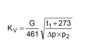
Calculation of th Kv value
The selection of a valve requires first of all that the Kv value is determined from the operating data under which the valve is to operate. As in most cases a table or diagram giving the specific volume of steam is not available, the formulae given below, which treat steam as an ideal gas, can be used to arrive at a sufficiently accurate result.
For subcritical pressure drops
use formula

or for supercritical pressure drops
use formula

The temperature of steam in its saturated state ( saturated steam ) may
be roughly calculated using the formula

Kv Flow Coeffizient m³/h
G Mass Flow kg/h
Q1 Volume Flow Upstream of the Valve m³/h
Q2 Volume Flow Downstream of the Valve m³/h
Δp Differential Pressure (p1 - p2) bar
p1 Inlet Pressure (abs.) bar
p2 Outlet Pressure (abs.) bar
t1 Temperature at Inlet °C
t2 Temperature of Saturated Steam °C
w1 Velocity Inside of the Pipeline before the valve m/s
w2 Velocity Inside of the Pipeline behind the valve m/s
d1 Nominal Diameter before the Valve mm
d2 Nominal Diameter behind the Valve mm
Calculating the nominal diameter
To keep pressure drop and noise within acceptable limits, certain flow velocities in the pipelines should not be exceeded. If no values have been specified we recommend the following:
» Exhaust steam 25 m/s
» Saturated steam 40 m/s
» Super heated steam 60 m/s
These rough guidelines apply to pipe diameters from DN 80 up. For smaller diameters lower flow velocities should be used. As in most cases the specific volume is not known, we use the following sufficiently accurate formula to calculate the volume:

Pipeline diameter can be calculated using following formula
For a given nominal diameter the flow velocity can be calculated as follows:


thanks for your visit