

AN INTRODUCTION TO THREAD TAPSوAN INTRODUCTION TO THREAD TAPS
A tap is a mechanical device applied to make a standard thread on a hole. A range of tap
pitch diameter (PD) limits, from which the user may select to suit local conditions, is available
standard ASME B94.9 Taps: Ground and Cut Threads (Inch and Metric Sizes) for straight
fluted taps, spiral pointed taps, spiral pointed only taps, spiral fluted taps, fast spiral fluted
taps, thread forming taps, pulley taps, nut taps, and pipe taps. The standard also gives the
thread limits for taps with cut threads and ground threads

Thread Form.
The basic angle of thread between the flanks of thread measured in an axial plane is 60 degrees. The line bisecting this 60° angle is perpendicular to the axis of the screw thread. The symmetrical height of the thread form, h, is found as follows:
The basic pitch diameter (PD) is obtained by subtracting the symmetrical single thread
height, h, from the basic major diameter as follows:
Dbsc = basic major diameter
P = pitch of thread
h = symmetrical height of thread
n = number of threads per inch
Types and Styles of Taps.
Tap type is based on general dimensions such as standard straight thread, taper and straight pipe, pulley, etc., or is based on purpose, such as thread forming and screw thread inserts (STI). Tap style is based on flute construction for cutting taps, such as straight, spiral, or spiral point, and on lobe style and construction for forming taps, such as straight or spiral.
Straight Flute Taps: These taps have straight flutes of a number specified as either standard
or optional, and are for general purpose applications. This standard applies to machine screw, fractional, metric, and STI sizes in high speed steel ground thread, and to machine screw and fractional sizes in high speed and carbon steel cut thread, with taper, plug, semi bottom, and bottom chamfer.

Spiral Pointed Taps: These taps have straight flutes and the cutting face of the first few threads is ground at an angle to force the chips ahead and prevent clogging in the flutes.This standard applies to machine screw, fractional, metric, and STI sizes in high speed steel ground thread, and to cut thread in machine screw and fractional sizes with plug, semibottom, and bottom chamfer.
 Spiral Pointed Only Taps: These taps are made with the spiral point feature only without longitudinal flutes. These taps are especially suitable for tapping thin materials. This standard
applies to machine screw and fractional sizes in high speed steel, ground thread, with plug chamfer.

Spiral Fluted Taps: These taps have right-hand helical flutes with a helix angle of 25 to 35 degrees. These features are designed to help draw chips from the hole or to bridge a keyway. This standard applies to machine screw, fractional, metric, and STI sizes in high speed steel and to ground thread with plug, semibottom, and bottom chamfer.

Fast Spiral Fluted Taps: These taps are similar to spiral fluted taps, except the helix angle is from 45 to 60 degrees.This standard applies to machine screw, fractional, metric, and STI sizes in high speed steel with plug, semibottom, and bottom chamfer

Thread Forming Taps: These taps are fluteless except as optionally designed with one or more lubricating grooves. The thread form on the tap is lobed, so that there are a finite number of points contacting the work thread form. The tap does not cut, but forms the thread by extrusion. This standard applies to machine screw, fractional, and metric sizes, in high speed steel, ground thread form, with plug, semibottom, and bottom entry taper.

Pulley Taps: These taps were originally designed for tapping line shaft pulleys by hand.Today, these taps have shanks that are extended in length by a standard amount for use where added reach is required. The shank is the same nominal diameter as the thread. This standard applies to fractional size and ground thread with plug and bottom chamfer.

Pipe Taps: These taps are used to produce standard straight or tapered pipe threads.This standard applies to fractional size in high speed steel, ground thread, to high speed steel and carbon steel in cut thread, and to straight pipe taps having plug chamfers and taper pipe taps.


Tap Marking
Ground thread taps specified in the U.S. customary system are marked with the nominal size, number of threads per inch, the proper symbol to identify the thread form, “HS” for high-speed steel, “G” for ground thread, and designators for tap pitch diameter and special features, such as left-hand and multi-start
threads.

Cut thread taps specified in the U.S. customary system are marked with the nominal size, number of threads per inch, and the proper symbol to identify the thread form. High-speed steel taps are marked “HS,” but carbon steel taps need not be marked.
Ground thread taps made with metric screw threads (M profile) are marked with “M,” followed by the nominal size and pitch in millimeters, separated by “X”. Marking also includes “HS” for high-speed steel, “G” for ground thread, designators for tap pitch diameter and special features, such as left-hand and multi-start threads

Standard System of Tap
Thread Limits and Identification for Unified Inch Screw Threads, Ground Thread.
H or L Limits: For Unified inch screw threads, when the maximum tap pitch diameter is over basic pitch diameter by an even multiple of 0.0005 inches, or the minimum tap pitch diameter limit is under basic pitch diameter by an even multiple of 0.0005 inches, the taps are marked “H” or “L”, respectively, followed by a limit number, determined as follows:
 Standard System of Ground Thread Tap Limits and Identification for Metric Screw Threads, M Profile
D or DU Limits: When the maximum tap pitch diameter is over basic pitch diameter by an even multiple of 0.013 mm (0.000512 in. reference), or the minimum tap pitch diameter limit is under basic pitch diameter by an even multiple of 0.013 mm, the taps are marked with the letters “D” or “DU,” respectively, followed by a limit number. The limit number is determined as follows:

TAP DRILL SIZE
Hole drilled to correct drill tap size for american thread tap
-leave proper amount of matrial of tap to cut thread (75 percent )
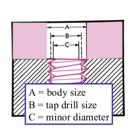
TDS : tap frill size
D: major diameter of tap
N: number of threads per inch
TAP DRILL SIZE FOR METRIC TAPS
metric thread taps uses


AN INTRODUCTION TO THREAD TAPS
introductionA tap is a mechanical device applied to make a standard thread on a hole. A range of tap
pitch diameter (PD) limits, from which the user may select to suit local conditions, is available
standard ASME B94.9 Taps: Ground and Cut Threads (Inch and Metric Sizes) for straight
fluted taps, spiral pointed taps, spiral pointed only taps, spiral fluted taps, fast spiral fluted
taps, thread forming taps, pulley taps, nut taps, and pipe taps. The standard also gives the
thread limits for taps with cut threads and ground threads

Thread Form.
The basic angle of thread between the flanks of thread measured in an axial plane is 60 degrees. The line bisecting this 60° angle is perpendicular to the axis of the screw thread. The symmetrical height of the thread form, h, is found as follows:
h =0.64951905 P =0.64951905 /n
height, h, from the basic major diameter as follows:
Basic Pitch Diameter = Dbsc – h
P = pitch of thread
h = symmetrical height of thread
n = number of threads per inch
Types and Styles of Taps.
Tap type is based on general dimensions such as standard straight thread, taper and straight pipe, pulley, etc., or is based on purpose, such as thread forming and screw thread inserts (STI). Tap style is based on flute construction for cutting taps, such as straight, spiral, or spiral point, and on lobe style and construction for forming taps, such as straight or spiral.
Straight Flute Taps: These taps have straight flutes of a number specified as either standard
or optional, and are for general purpose applications. This standard applies to machine screw, fractional, metric, and STI sizes in high speed steel ground thread, and to machine screw and fractional sizes in high speed and carbon steel cut thread, with taper, plug, semi bottom, and bottom chamfer.

Spiral Pointed Taps: These taps have straight flutes and the cutting face of the first few threads is ground at an angle to force the chips ahead and prevent clogging in the flutes.This standard applies to machine screw, fractional, metric, and STI sizes in high speed steel ground thread, and to cut thread in machine screw and fractional sizes with plug, semibottom, and bottom chamfer.

applies to machine screw and fractional sizes in high speed steel, ground thread, with plug chamfer.

Spiral Fluted Taps: These taps have right-hand helical flutes with a helix angle of 25 to 35 degrees. These features are designed to help draw chips from the hole or to bridge a keyway. This standard applies to machine screw, fractional, metric, and STI sizes in high speed steel and to ground thread with plug, semibottom, and bottom chamfer.

Fast Spiral Fluted Taps: These taps are similar to spiral fluted taps, except the helix angle is from 45 to 60 degrees.This standard applies to machine screw, fractional, metric, and STI sizes in high speed steel with plug, semibottom, and bottom chamfer

Thread Forming Taps: These taps are fluteless except as optionally designed with one or more lubricating grooves. The thread form on the tap is lobed, so that there are a finite number of points contacting the work thread form. The tap does not cut, but forms the thread by extrusion. This standard applies to machine screw, fractional, and metric sizes, in high speed steel, ground thread form, with plug, semibottom, and bottom entry taper.

Pulley Taps: These taps were originally designed for tapping line shaft pulleys by hand.Today, these taps have shanks that are extended in length by a standard amount for use where added reach is required. The shank is the same nominal diameter as the thread. This standard applies to fractional size and ground thread with plug and bottom chamfer.

Pipe Taps: These taps are used to produce standard straight or tapered pipe threads.This standard applies to fractional size in high speed steel, ground thread, to high speed steel and carbon steel in cut thread, and to straight pipe taps having plug chamfers and taper pipe taps.


Tap Marking
Ground thread taps specified in the U.S. customary system are marked with the nominal size, number of threads per inch, the proper symbol to identify the thread form, “HS” for high-speed steel, “G” for ground thread, and designators for tap pitch diameter and special features, such as left-hand and multi-start
threads.

Cut thread taps specified in the U.S. customary system are marked with the nominal size, number of threads per inch, and the proper symbol to identify the thread form. High-speed steel taps are marked “HS,” but carbon steel taps need not be marked.
Ground thread taps made with metric screw threads (M profile) are marked with “M,” followed by the nominal size and pitch in millimeters, separated by “X”. Marking also includes “HS” for high-speed steel, “G” for ground thread, designators for tap pitch diameter and special features, such as left-hand and multi-start threads

Standard System of Tap
Thread Limits and Identification for Unified Inch Screw Threads, Ground Thread.
H or L Limits: For Unified inch screw threads, when the maximum tap pitch diameter is over basic pitch diameter by an even multiple of 0.0005 inches, or the minimum tap pitch diameter limit is under basic pitch diameter by an even multiple of 0.0005 inches, the taps are marked “H” or “L”, respectively, followed by a limit number, determined as follows:

D or DU Limits: When the maximum tap pitch diameter is over basic pitch diameter by an even multiple of 0.013 mm (0.000512 in. reference), or the minimum tap pitch diameter limit is under basic pitch diameter by an even multiple of 0.013 mm, the taps are marked with the letters “D” or “DU,” respectively, followed by a limit number. The limit number is determined as follows:

Hole drilled to correct drill tap size for american thread tap
-leave proper amount of matrial of tap to cut thread (75 percent )

TDS = D-1/N
whereTDS : tap frill size
D: major diameter of tap
N: number of threads per inch
TAP DRILL SIZE FOR METRIC TAPS
TDS = major diameter (mm) - pitch (mm)
metric thread taps uses


thanks for your visit