

An Introduction To Positive Displacement Pump
Types Selection and Applications
Introduction
A Positive Displacement Pump has an expanding cavity on the suction side and a decreasing cavity on the discharge side. Liquid flows into the pumps as the cavity on the suction side expands and the liquid flows out of the discharge as the cavity collapses. The volume is a constant given each cycle of operation.
The positive displacement pumps can be divided in two main classes
- reciprocating
- rotary
The positive displacement principle applies whether the pump is a
- rotary lobe pump
- progressing cavity pump
- rotary gear pump
- piston pump
- diaphragm pump
- screw pump
- gear pump
- vane pump
- regenerative (peripheral) pump
- peristaltic
Typical reciprocating pumps are
- plunger pumps
- diaphragm pumps
In a diaphragm pump the plunger pressurizes hydraulic oil which is used to flex a diaphragm in the pumping cylinder. Diaphragm pumps are used to pump hazardous and toxic fluids.


Types Selection and Applications
Introduction
A Positive Displacement Pump has an expanding cavity on the suction side and a decreasing cavity on the discharge side. Liquid flows into the pumps as the cavity on the suction side expands and the liquid flows out of the discharge as the cavity collapses. The volume is a constant given each cycle of operation.

Pump Types
PD pumps can be divided into two broad classifications, reciprocating and rotary. Figure 1 illustrates the classes, categories, and types of PD pumps utilized in the industry. The principles of both reciprocating and rotary type pumps, common terminologies of PD pump, and PD pump applications are discussed in the following sections
The positive displacement pumps can be divided in two main classes
- reciprocating
- rotary
 |
| FIG 1 |
- rotary lobe pump
- progressing cavity pump
- rotary gear pump
- piston pump
- diaphragm pump
- screw pump
- gear pump
- vane pump
- regenerative (peripheral) pump
- peristaltic
Reciprocating Pumps
- plunger pumps
- diaphragm pumps
 |
| FIG 2 |
A reciprocating positive displacement pump is one in which a piston or plunger displaces a given volume of fluid for each stroke. The reciprocating pumps can also be categorized in different ways such as single acting or double acting; direct acting or indirect acting; and simplex or duplex. Reciprocating pumps are used in power plants for chemical feed system, fuel oil system, lubricating oil system, or hydrostatic pressure test.
 |
| FIG 3 |
Rotary Pumps
Rotary pumps operate in a circular motion and displace a constant amount of liquid with each revolution of the pump shaft. In general, this is accomplished by pumping elements moving in such a way as to expand volumes to allow liquid to enter the pump and discharge a smooth flow. Pumping element designs include gears, lobes, vanes, and screws . Rotary pumps are found in a wide range of applications due to their relatively compact design, high viscosity performance, continuous flow (regardless of differential pressure), and the ability to handle high differential pressure.
Gear Pumps
The most common type of rotary pump is the gear pump. In gear pumps, two or more gears mesh to provide the pumping action. The two main types of gear pumps are internal and external . Internal gear pumps carry fluid between the gear teeth from the inlet to outlet ports. External gear pumps carry fluid between the teeth and the casing.
 |
| FIG 4 |
Lobe Pumps
The lobe pump, shown on the right, receives its name from the rounded shape of the rotor radial surfaces, which permits the rotors to be continuously in contact with each other as they rotate. Fluid is carried between the rotor teeth and the pumping chamber
 |
| FIG 5 |
Vane Pumps
The vane pumps have movable sealing elements in the form of rigid blades, rollers, buckets, or slippers. The vanes work with a cam to draw fluid into and force it out of the pump chamber,
as shown.
 |
| FIG 6 |
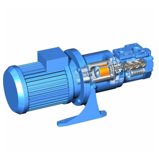
Screw Pumps
Screw pumps carry fluid in the spaces between the screw threads. The fluid is displaced axially as the screw(s) mesh. Single screw pumps are commonly called progressive cavity pumps. They have a rotor with external threads and a stator with internal threads. The rotor threads are eccentric to the axis of rotation. Screw pumps are classified into single and multiple rotor types. Multiple rotor are the most common.
 |
| FIG 7 |
Pump Selection
The following factors are commonly considered for the selection of PD pumps vs. centrifugal pumps:
· Self priming
· Abrasion resistance
· Control requirements
· Variation in flow
· Viscosity
· Fluid Density
· Corrosion
Additionally, the selection of pump class and type for a particular application is also influenced by factors such as system layout, intended life, energy cost, code requirements, and materials of construction. Figure 8 shows the differences between PD and centrifugal pumps in terms of performance, flow rate with various viscosity, and efficiency.
 |
| FIG 8 |
Common Characteristics of PD Pumps
Besides higher overall efficiency than centrifugal pumps (because internal losses are minimized), other common characteristics of PD pumps are:
1. Adaptable to high pressure operation
2. Variable flow rate through the pump is possible
3. Maximum throughputs are limited by mechanical considerations
4. Capable of efficient performance at extremely low volume throughput rates.
Pump and Head Terminology
The principle of conservation of energy states that the total energy input to a closed system is equal to the total energy output from that system. The energy in the fluid at Points 1 and 2 (as shown in Figure 9) can be restated by the following Bernoulli’s equation.
 |
| FIG 9 |

where:
P₁, P₂ = Pressure at Points 1 and 2
ρ = Fluid Density
Z₁, Z₂ = Static Elevation at Points 1 and 2
V₁, V₂ = Velocity at Points 1 and 2
Ep = Energy Added by Pump
hf = Friction Loss Between Points 1 and 2
Fluid flow energy is often expressed as fluid “head” in units of feet. The following terminology applies to the Bernoulli’s equation.
· Pressure head, hp = P / ρ is the pressure energy
· Elevation head, he = Z, is the potential energy
· Velocity head, hv = V²/2𝙜 is the kinetic energy
· Pump head, Ep is the increase in fluid flow energy resulting from the pump work.
· Friction head, hf is the energy required to overcome the resistance to flow in the pipe, fittings, valves, entrances, and exits.
· Static suction head, hs is the vertical distance in feet above the centerline of the pump inlet to the free level of the fluid source.
· Static discharge head, hd is the vertical distance in feet above the pump centerline to the free level of the discharge tank.
· Net suction head, Hs is the total energy of the fluid entering the pump inlet.

· Total dynamic head, H is the net discharge head minus the net suction head. It is the amount of energy added to the fluid by the pump.

PD Pumps Calculations
The displacement is a function of the area of the liquid piston and the speed at which the piston is moving. The displacement of a single piston can be calculated from the formula
D= (A×n× s)/231
Where
D = pump displacement, gallons per minute
A = area of the piston or plunger, inch²
n = rpm or strokes per minute of pump
s = stroke length, inches
231 = inch³/gal (conversion factor)
Brake horsepower for the pump is:

Where whp = water horsepower
Bhp = brake horsepower
Q = pump capacity, gpm
Pl = net liquid pressure, lb/in²
Em = mechanical efficiency (% as a decimal)
In a rotary pump the liquid displaced by each revolution of the pump is independent of the pump speed. The pump capacity, Q is equal to:
D = k Drp n – S
Where:
D= displacement capacity, gallons per minute
k = 0.004329, gallon/cubic inch (conversion factor)
Drp = rotary pump displacement, cubic inches per revolution
n = pump speed, revolutions per minute
S = pump slip, gallons per minute
Pump speed is the number of revolutions of the driving, or main, rotor per unit time. Pump pressure is the absolute pressure of the fluid at any location in the pump. Several pressure terms of interest are briefly discussed below.
·Velocity pressure Pv is the pressure caused by fluid velocity which mostly small relative to the total pressure and may be caused by the fluid velocity, which is typically small enough to be neglected.
·Outlet pressure Pd is the total pressure at the outlet of the pump. The outlet pressure is commonly expressed as the gage pressure which is the difference between the absolute pressure and atmospheric pressure at the outlet port.
·Inlet pressure Ps is the total pressure at the inlet to the pump. The pump differential pressure Ptd is the difference between the outlet pressure and the inlet pressure.
Ptd = Ps -Pd
Pump power is the total power required by the pump driver or the pump prime mover under given operating conditions. The pump power output can be computed by the following equations:

where:
whp = water horsepower which is equal to 550 ft lb/s
kW = kilowatt
Q = gallons per minute in whp equation or cubic meters per minute in kW equation
Ptd = pounds per square inch
Pump efficiency or pump mecha nical efficiency is the ratio of the rotary pump power output to the pump input. The difference between pump power input and output actually consists of three power losses represented by pump slip, mechanical friction in the pump, and fluid friction.


thanks for your visit